Introduction
Playing with dice is an age old game. We all love to play with it too. Playing with dice needs us to pick up a dice and make sure that it is unbiased. Making a block as a dice and cutting it clearly to make sure that it is unbiased is all an old story. The dice becomes biased if the shape is not cut well. Also, the dice can become biased due to deformations. If it is a wooden die, it can deform due to dampness in the atmosphere or due to mechanical stress. To solve all these problems which we have with a conventional dice, we have made a dice circuit which solves all the problems of a conventional dice. Now, we are going to show you an electronic LED dice which is nearly unbiased. There is no chance to cheat as the circuit operates at such a high speed that the circuit is almost imperceptible to the human eye. There is also little maintenance and there is hardly any impact on aging of the circuit. The frequency may vary a bit with change in power supply voltage, aging of the active and passive components but still the randomness will be preserved without any trouble.
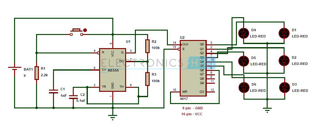
Electronic LED Dice Circuit Diagram
Components Required
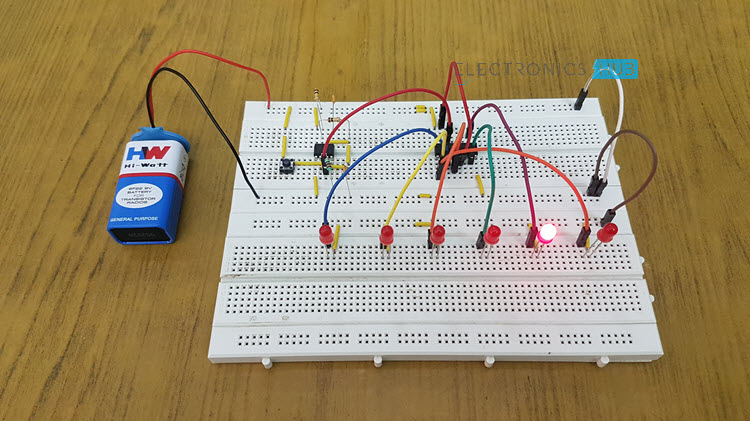
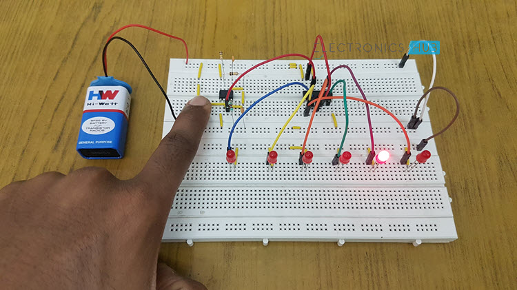
LEDs X 6 555 Timer IC CD4017 Decade Counter IC Resistors – 2.2KΩ, 100KΩ X 2 Capacitors – 1nF and 0.1µF Push Button 9V Battery Breadboard Connecting Wires
Operation of Unbiased Electronic Dice with LEDs
This circuit uses 555 timer as an astable multivibrator. In this mode, the circuit is arranged with R2 = 100 KΩ, R3 = 100 KΩ and C2 = 0.1 µF. With this configuration, the circuit operates as a pulse generator with a frequency in order of kilo hertz. This means that the circuit produces a clock cycle of about 0.000210 seconds which is imperceptible to the human eye. We cannot observe the values which change at that faster rate so there is hardly any possibility of getting the dice biased. The clock pulses are given to a counter cum decoder circuit IC 4017 with the seventh output given to reset. It has nine possible outputs out of which, the seventh is given to reset because we only need a count up to 6 as a dice has six faces only. The first six outputs are given respectively to the LEDs, so that the respective LED will glow for the corresponding count.
If the count is 1, LED-1 will glow. If the count if 2, LED-2 will glow and so on until the sixth count. When the count is six, the sixth LED will glow and after that for the next clock pulse the counter will advance and the count increments to seven. In this count, the circuit resets itself as the seventh count is given to the reset pin which is PIN-15. Let me tell you that the power supply pin and ground are not shown in the circuit diagram as it is the schematic generated by the software Proteus. However, the power supply of 9V is given to the 16th pin of IC 4017 and the 8th pin of IC 4017 is given to ground. This is how the circuit functions and you can increase the frequency of the circuit if you feel that you need more randomness so that it is very hard to perceive. This circuit can be implemented on a general purpose PCB with a 9V DC power supply.
Applications
This unbiased electronic dice with LEDs can be used wherever traditional dice is used like:
Snakes and Ladders Chutes and Ladders Ludo Monopoly Business
Note:
For more electronics circuits, follow the link: Free Electronics Project Circuits
For High Level: T1 = 0.693 * C2 * (R2+R3) For High Level: T1 = 0.693 * R2 * C1 Comment * Name * Email * Website
Δ
![]()
![]()
![]()
![]()
![]()

