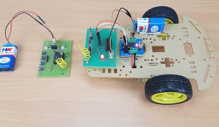
We have seen many types of Robotic Vehicles like Line Follower Robot, Bluetooth Controlled Robot, DTMF Controlled Robot, Gesture Controlled Robot, etc. but what make the RF Controlled Robot a unique project is it doesn’t use programming or a Microcontroller to control the robot and the range between the transmitter (remote control) and receiver (robot) can be significantly larger than other types. NOTE: Even a DTMF based Robotic Vehicle can be implemented without a Microcontroller. A simple RF Controlled Robot using 434 MHz RF (Radio Frequency) Transmitter and Receiver Pair , a Motor Driver IC (L293D) is implemented here.
Circuit Diagram of the Transmitter
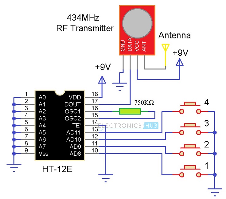
The circuit diagram of the Transmitter part of the Robot is shown below. It consists of a 434 MHz RF Transmitter Module paired with HT-12E Encoder IC and four push buttons.
Components Required for Transmitter Circuit
434 MHz RF Transmitter Module HT-12E Encoder IC 750 KΩ Resistor (1/4 W) Small Push Buttons x 4 9V Battery Jumper Wires
Circuit Diagram of the Receiver
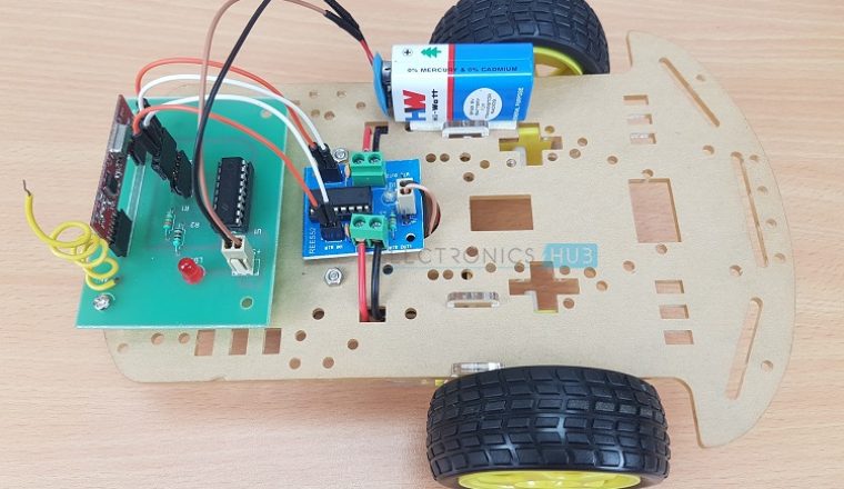
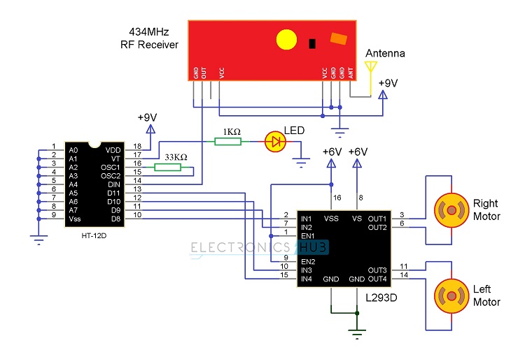
The circuit diagram of the Receiver part of the Robot consists of a 434 MHz RF Receiver Module paired with HT-12D Decoder IC, Small Robot Chassis, two small motors (geared type) and an L293D Motor Driver IC.
Components Required for Receiver Circuit
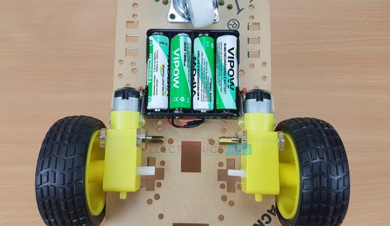
434 MHz RF Receiver Module HT-12D Decoder IC 33 KΩ Resistor (1/4 W) L293D Motor Driver IC Small Geared Motor x 2 1 KΩ Resistor (1/4 W) LED 9V Battery 1.5 V AA Battery x 4 Robot Chassis Jumper Wires
Brief Note on RF Transmitter and Receiver
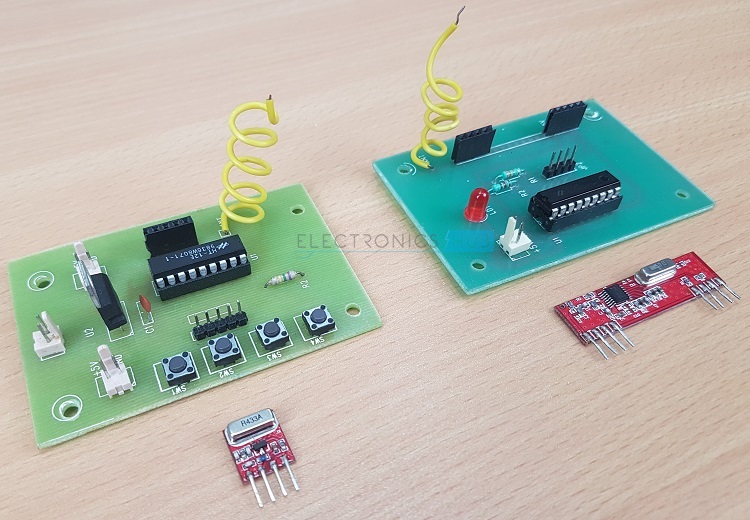
RF Transmitter and Receiver Pair provide wireless communication between two devices that are separated by a distance. RF Transmitter and Receiver Pair work on the Radio Frequency Technology that transmit data through space using Electromagnetic Waves. The range of frequencies used for Radio Communication is very wide i.e. between 3 KHz to 300 GHz. For consumer and commercial applications, we often use RF Modules working in the carrier frequency bands of 315 MHz, 868 MHz (unlicensed frequencies for short range communication), 433.92 MHz (434 MHz), 915 MHz and 2.4 GHz ISM bands. The RF Transmitter and Receiver Pair used in this project uses a carrier frequency of 433.92 MHz and are shown in the following image.
The information between the RF Transmitter and Receiver Modules is ASK (Amplitude Shift Keying) modulated. We often use Encoder and Decoder ICs with Transmitter and Receiver modules for encoding and decoding the information.
Circuit Design of Transmitter Part
The address pins of HT-12E Encoder i.e. pin 1 to 8 (A0 to A7), the Transmission enable pin (Pin 14) and the VSS pin (pin 9) are all connected to GND. The four Address/Data Pins i.e. pins 10 to 13 (AD8 to AD11) are connected to one end of four push buttons while the other ends of the push buttons are connected to GND. A 750 K ohm Resistor is connected between OSC1 and OSC2 pins (pin 16 and 15) to enable the internal oscillator. The DOUT pin (Pin 17) is connected to the Data Pin of the RF Transmitter Module. VDD (Pin 18) is connected to 9V power supply. Coming to the RF Transmitter Module the VCC and GND pins are connected to +9V and GND respectively. For the antenna, connect a wire (twisted as a coil or a straight wire) of about 10CM in length.
Circuit Design of Receiver Part
Since all the address pins of the Encoder IC are connected to GND, connect all the Address Pins of the Decoder IC i.e. A0 to A7 (pins 1 to 7) to GND. The Data Pins of the Decoder i.e. D8 to D11 (pins 10 to 13) must be connected to the Input pins of the Motor Driver IC (i.e. D8 to IN1, D9 to IN2, D10 to IN3 and D11 to IN4). The DIN pin (Pin 14) is connected to the OUT pin of the RF Receiver Module. A 33 KΩ resistor is connected between pins 16 and 15 (OSC1 and OSC2). An LED with 1 KΩ current limiting resistor is connected to the Valid Transmission pin (Pin 17). The VDD and VSS pin are connected to +9V and GND. Two Motors are connected to the Motor Driver at the OUT1 and OUT2 (Right Motor) and OUT3 and OUT4 (Left Motor). NOTE: We have used Modules for both RF Transmitter part and Receiver part which includes connections for encoder and decoder ICs and push buttons. If you want to build this circuit on breadboard, refer this link.
Working of the Project
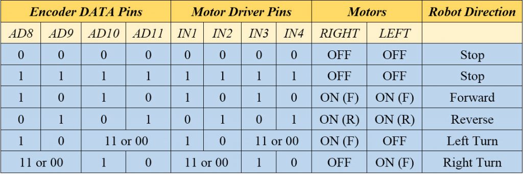
A simple RF Controlled Robot without using any microcontrollers is designed in this project. Let us see its working. First, let us refer the datasheet of the HT-12E Encoder IC. When the TE (Transmission Pin) is enabled (active low pin, hence to enable it, we need to connect it to GND), the DATA pins (AD8 to AD11) are set to HIGH by default. Individual buttons are pushed to make DATA pins LOW. Before turning ON the RF Receiver Module, we need to turn on the RF Transmitter module first. Since no button is pressed, Encoder IC transmits logic highs on all Data Pins. This data is transmitted through the RF Channel using the RF Transmitter and is received by the RF Receiver. The Received data is decoded by Decoder IC and the data available at the data out of the Decoder IC is logic high on all pins. Since the data pins of the Decoder are connected to the input of the motor driver and as all the pins are high, both the motors are off and the Robot is in stop position. The following table shows some of the possible combinations of data on the Encoder IC and the resultant effect on the motors connected to the motor driver.
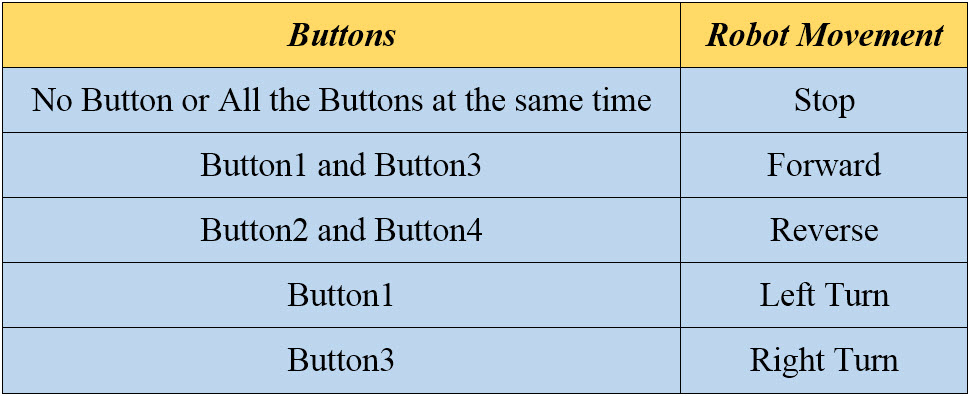
When a button is pressed on the Transmitter, the corresponding data pin receives a logic low value. Depending on the combination of the buttons pressed, the RF Controlled Robot will move accordingly. Assume the Button connected to AD8 of the Encoder IC as Button1, button connected to AD9 as Button2 and so on. When no button is pressed or all buttons are pressed at the same time, the robot stays still. When Button1 and Button3 are pressed, the robot will move in forward direction. When Button2 and Button4 are pressed, the robot will move in reverse direction. The following table shows the possible combination of Buttons for different movements of the Robot.
NOTE: The movement of the robot depends on how you connect the data pins and the also the motor.
Advantages of RF Controlled Robot
Since, the communication in RF Controlled Robot is based on RF Technology, there is no need for line of sight communication and hence this types of robots can be used in Defense, Surveying, Mining and other similar applications. The range of communication between the RF Transmitter and Receiver can be stretched to more than 50 Meters with the use of appropriate antenna. There is no microcontroller in the project and hence can be implemented with out any requirement of programming knowledge.
Disadvantages
We need to press more than one button at the same time for certain operations of the robot. The distance between the transmitter and receiver is limited in indoor conditions.
Construction and Output Video
Comment * Name * Email * Website
Δ
![]()
![]()
![]()

![]()
![]()

