The distance between car and obstacle is understood by the group of LED’s (D5 to D7). If the distance between car and obstacle is 25cm then D7 will glow. At the distance of 20cm D7 and D6 LEDs turn ON and at a distance of 5cm all LED’s (D5, D6, D7) glow. When the distance is more than 25cm then all LED’s will turn off.
Reverse Parking Sensor Circuit Principle:
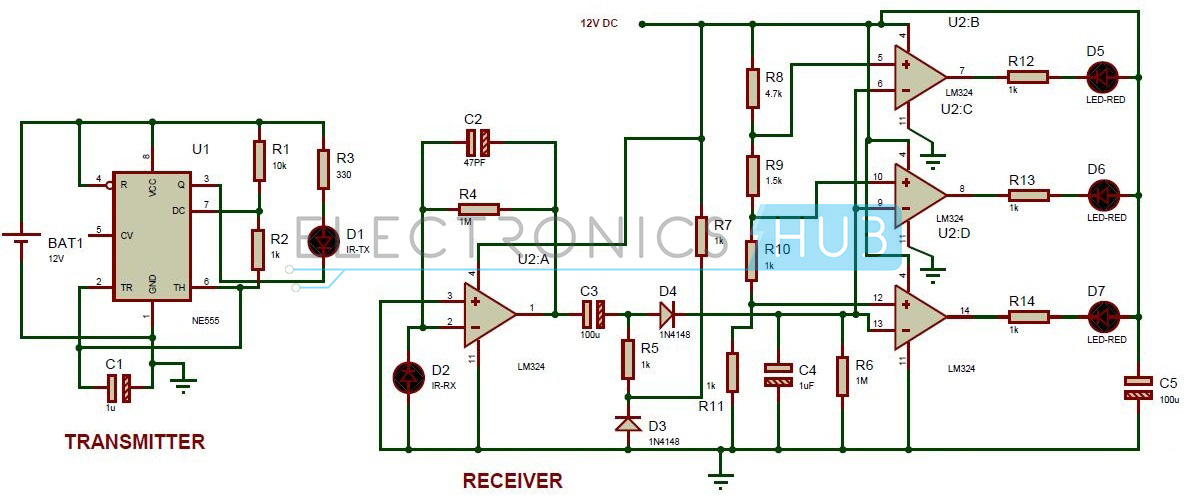
Parking sensor circuit mainly consists of two sections, one is transmitter section and the other is receiver section. The transmitter section uses NE555 timer IC as an astable multivibrator for driving the IR transmitter. The transmitter frequency is set to be 120Hz. The IR pulses transmitted by the IR transmitter are reflected back because of the obstacle and received by the IR receiver. The received signal is amplified by the U2:A. The output voltage of the Peak detector (R4 and c4) is proportional to the distance between car bumper and obstacle. The output voltage of the peak detector is given to the inputs of three comparators U2: B, U2: C and U2:D. These comparators switch the status LED’s according to the input voltage and the reference voltage.
Reverse Parking Sensor Circuit Diagram:
Circuit Components: Transmitter:
NE555 timer IR transmitter Electrolytic capacitor – 1uF, 16V Resistors – 10k, 1k, 330 ohm
Receiver:
LM324 IC (low power quad op-amp) IR receiver 1n4148 diodes – 2 Electrolytic capacitors – 100u (2), 10u, 47p, 1u LED’s – 3 (5mm) 1k resistors – 7 1M ohm resistors – 2 4.7k , 1.5k resistors 12V DC battery Connecting wires
Reverse Parking Sensor Circuit Design:
In transmitter section, 555 timer is operated in astable mode to generate a signal with frequency of 120 Hz. The 4th pin of 555 timer is connected to supply to avoid sudden resets. The output pulse is produced at 3rd pin of 555 timer. Here resistors R1, R2 and C1 set the output frequency of 555 timer. The received by the IR receiver is amplified the by the operational amplifier U2:A. Resistor R4 and C4 forms peak detector to detect peak of the amplified signal. Op – amp as Comparator: Op-amp has two inputs (non-inverting and inverting) and one output. The output of operational amplifier is high when non-inverting voltage is greater than inverting voltage. The output voltage is low, when inverting voltage is greater than non-inverting voltage. In the above circuit the voltages at non inverting pins of comparators acts as a reference voltage and inverting input voltages at comparators are compared with reference voltages to produce the output. Here resistors R8 to R11 are used to set different reference voltages at their non inverting pins. Resistors R12, R13 and R14 are used to protect the LED’s from high voltages.
How to Operate this Reverse Parking Sensor Circuit?
Reverse Parking Sensor Circuit Applications:
This circuit can be used in auto mobiles to park the vehicle safely. We can use this circuit to measure the distance. We can also use this circuit as IR Liquid Level Detector by making few modifications.
IR receiver may receive the normal light. As a result, parking sensor may not work properly. We should arrange IR sensors accurately; otherwise they may not detect the obstacle.
Comment * Name * Email * Website
Δ
![]()
![]()
![]()
![]()
![]()

