Water is a basic need in every one’s life. Saving water and proper usage of water is very important. Here is an easy project which will give the alarm when there is rain, so that we can make some actions for rain water harvesting and also save the rain water for using it later. With the help of saving this rain water through rain water harvesting, we can increase the levels of underground water by using underwater recharge technique. Rain water detector will detect the rain and make an alert; rain water detector is used in the irrigation field, home automation, communication, automobiles etc. Here is the simple and reliable circuit of rain water detector which can be constructed at low cost. In this project, we have designed a simple Rain Alarm Circuit, which, upon detecting rain, will activate a buzzer. Based on the buzzer, we can take necessary actions.
Circuit Diagram
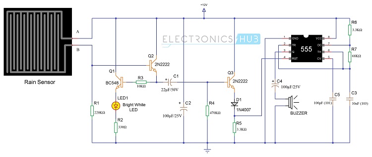
The circuit diagram from the Rain Alarm Project is shown in the below image.
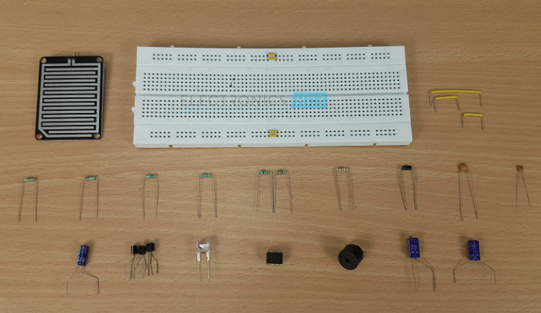
Components Required
1 x Small Rain Sensor 1 x 555 Timer IC 1 x BC548 NPN Transistor 2 x 2N2222 NPN Transistor 1 x Bright White LED 1x 1N4007 PN Junction Diode 1 x 220 KΩ Resistor (1/4 Watt) 1 x 330 Ω Resistor (1/4 Watt) 1 x 10 KΩ Resistor (1/4 Watt) 1 x 470 KΩ Resistor (1/4 Watt) 2 x 3.3 KΩ Resistor (1/4 Watt) 1 x 68 KΩ Resistor (1/4 Watt) 1 x 22 µF Capacitor (Polarized) 2 x 100 µF Capacitor (Polarized) 1 x 10nF Ceramic Capacitor (Code – 103) 1 x 100pF Ceramic Capacitor (Code – 101) 1 x Buzzer (or Speaker – 8Ω) Connecting Wires Breadboard 12V Power Supply
Rain Alarm Project Block Diagram
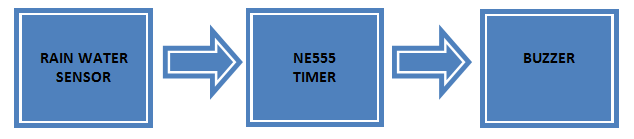
The block diagram of the Rain Alarm Project is shown in the following image. The three main components of the project are the Rain Water Sensor, 555 Timer IC and Buzzer. When the Rain Water Sensor detects the Rain, it sends a signal to the 555 Timer. The 555 Timer IC, which is configured in its Astable Mode, will then activate the Buzzer.
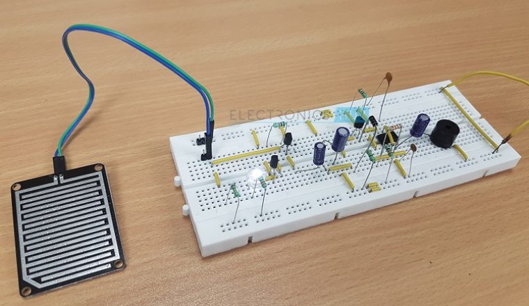
Rain Water Sensor
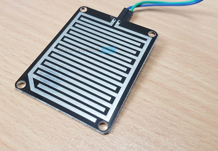
The Rain Water Sensor used in this project is shown in the image below. It is a simple sensor and it is an easy to use tool for detecting rain. It can act as a simple switch, where the switch is normally open and when there is rain, the switch closes.
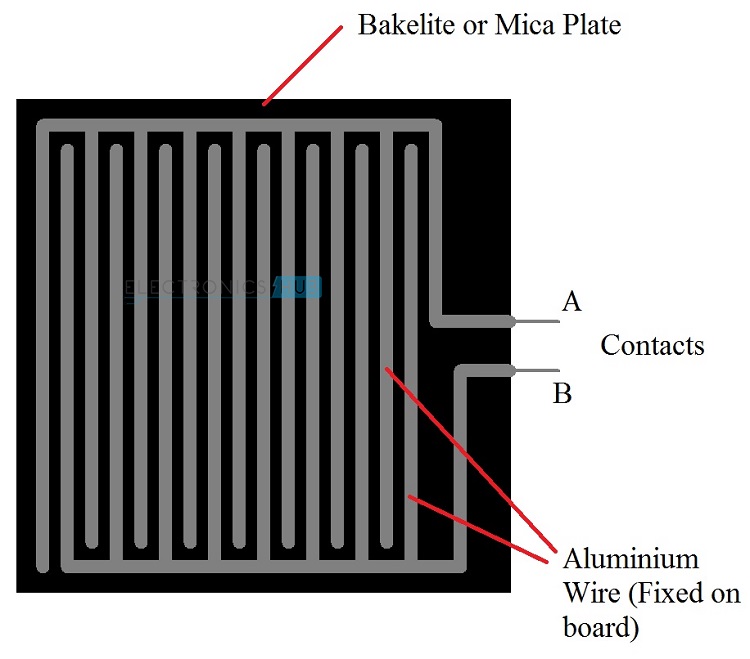
Even though Rain Water sensor is the main component in the circuit. We need not to go and buy in the market or online. We can do it ourselves just by taking the piece of Bakelite or Mica board and aluminium wire. Bakelite or Mica board should be made completely flat and aluminium wire should be pasted on the flat board as shown in the figure below. Care should be taken that there should be no spaces between the wire and board. When the rain water sensor is completed, it should get connected to the circuit and voltage should be passed through the wires. If there is no rain, the resistance between the contacts will be very high as there will be no conduction between the wires in the sensor. If there is rain, the water drops will fall on the rain sensor, which will form a conductive path between the wires and it also decreases the resistance between the contacts. As a result, the wires on the sensor board will conduct and trigger the NE555 timer through the transistors circuitry. Once NE555 is triggered, it will make the output pin high and which will make the buzzer to make alarm.
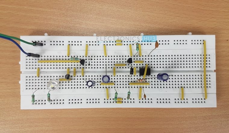
Working of the Circuit
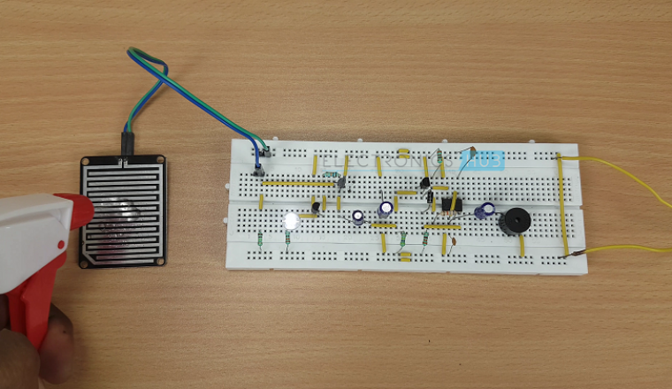
We will see the working of the simple Rain Sensor Alarm Circuit Project. When rain falls on the sensor, the Aluminium Wires on the Sensor Board will start conducting and close the path between the supply and base of the transistor Q2. As a result, the Transistor Q2 will turn ON, which will also turn ON the Transistor Q1. This will turn ON the Bright White LED connected to the emitter of the Transistor Q1. When the transistor Q2 is saturated, the capacitor C1 will be shorted and will make the transistor Q3 to be turned ON. C1 will get charged by the resistor R4. When the Transistor Q3 reaches the saturation mode, the Reset Pin of the 555 Timer IC, which is connected to the emitter of Q3, will be made positive. The 555 timer is configured in Astable Mode. As the Reset pin of the 555 Timer IC is given positive voltage, it becomes active and we will get a Pulse signal at the output pin 3 of the 555 Timer IC. This will turn ON the buzzer and the alarm is activated. If you are using a speaker, Capacitor C4, which is connected in between the Pin 3 of 555 timer and the speaker, will block the DC signal and allows only the variations in the signal which makes the speaker to make sound. The diode D1 will not allow any reverse current from the timer. Because of the resistor R4 and capacitor C1, when the capacitor is completely charged, the transistor Q3 will get in to cut – off mode after sometime. As a result, the Reset pin of the 555 Timer IC will not receive any positive voltage and the speaker will stop making sound. The time for 555 Timer to make speaker sound depends on the values of C1 and R4. When there is no rain, the aluminium wire on the sensor will not conduct as they do not have any conduction path (open circuit). As a result, the sensor cannot trigger the 555 Timer IC and there will be no alarm. Note:
Rain senor should be kept in the open place at 30 to 40 degrees from the ground. As a result, rain water will not be present on the sensor for long time. This circuit will automatically switch of the alarm after sometime and LED will glow continuously until the rain stops.
Rain Alarm Project Circuit Applications:
Comment * Name * Email * Website
Δ
![]()
![]()
![]()

![]()
![]()

