Principle behind the Circuit
The main principle of this circuit is based on the working of the LDR Sensor i.e. the Light Dependent Resistor and to switch ON or OFF the light based on the intensity of illumination the LDR is subjected to. Speaking of the light dependent resistor, it will have a high resistance in darkness and low resistance in the presence of light. This property of the LDR is used with a comparator circuit. More information can be found in the working.
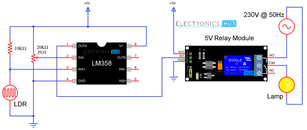
Light Activated Switch Circuit Diagram
Circuit Components
LM358 Comparator IC Relay Module Light Dependent Resistor LDR 10KΩ Resistor 20KΩ Potentiometer Bulb Connecting Wires Mini Breadboard 5V Power Supply
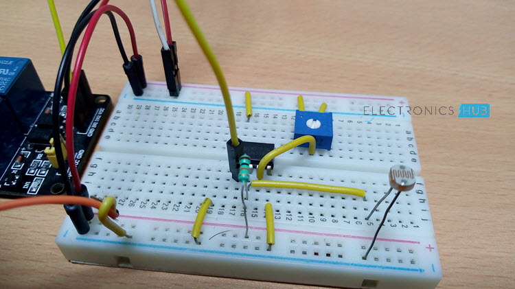
Light Activated Switch Circuit Design
The light activated switch circuit mainly consists of two components: the comparator IC LM358 and the LDR. The LM358 IC has 8-pins and can have supply voltages ranging from 3-32 volts. It has two internally frequency compensated operational amplifiers. In the present circuit, only one op-amp is used for comparing the input voltages. Out of the eight pins of LM358, pins 1, 2 and 3 are used by the first op-amp while pins 5, 6 and 7 are used by the second Op-Amp. Pins 4 and 8 are common for both the op amps as they are GND and VCC Pins. Since I’m using only one Op-Amp (the first one), I will design the circuit using pins 1, 2, 3, 4 and 8. Pin 3 is the inverting pin of the Op-amp. Its input is given from the combination of the Light Dependent Resistor (LDR) and a 10KΩ Resistor. Pin 2 is the non-inverting pin and its input is given from the potentiometer. Pin 8 is connected to the supply voltage of +5V while the pin 4 is connected to the ground.
NOTE:
The Light dependent resistor has high resistance value in darkness and as intensity of light illuminating on the resistor increases, its resistance value decreases. Here, a 2MΩ Light Dependent Resistor is used. It has resistance value ranging from 2KΩ ohms to 2MΩ.
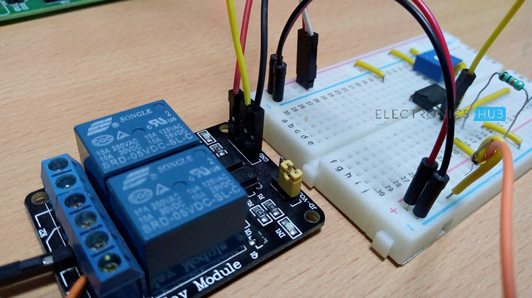
The output of the Op-Amp i.e. its Pin 1 is connected to the IN Pin of the Relay Module. Since I have used a 5V Relay Module, its Vcc and GND pins are connected to +5V and GND respectively. Coming to the Bulb connection, there are three pins for connecting a load to the relay. They are: Normally Open NO, Normally Closed NC and COM. Initially, the COM pin is connected to the Normally Closed i.e. NC Pin. When the relay is activated i.e. appropriate voltage is applied to the coil of the relay, the COM pin is connected to the Normally Open pin. Hence, connect one end of the light bulb to the COM pin of the relay and the other is connected to one wire of the AC Mains Supply. The other wire of the mains supply is connected to the Normally Open pin of the relay. CAUTION: You have to be extremely when working with AC Mains Supply. Adult or expert supervision is recommended.
Working
The working of this project is very simple and in fact if you are familiar with LDR and comparator, then you might have already understood the working. When the light falls on the Light Dependent Resistor, the comparator compares the voltages at the non-inverting pin and the inverting pin of the op-amp. If the voltage at the non-inverting pin is greater than the voltage at the inverting pin, its output will be LOW and if the voltage at non-inverting pin is less than the voltage at the inverting pin, the output of the comparator will be HIGH. In my case, under normal room light conditions, the output of the Op-Amp is LOW and hence, the Light Bulb stays OFF. When I apply some light on the LDR (with the help of a small torch), the output of the Op-Amp becomes HIGH and the Light Bulb turns ON.
Light Activated Switch Circuit Simulation Video
How to Operate this Light Activated Switch Circuit?
Link to Old Output Video
Light Activated Switch Circuit Applications
This circuit can be used in security applications like when there is darkness on the LDR, it stops lighting. This can be used in applications where the light is switched on /off depending on the ambient light
Comment * Name * Email * Website
Δ
![]()
![]()
![]()
![]()
![]()

