If you want to connect I2C LCD with ESP8266 NodeMCU board, then I made a separate tutorial just for that. Check it out.
Introduction
There are many display devices like OLED Display, 128×64 Graphical Display, Nokia 5110 Display etc. But for displaying simple text and number, all we need is a 16×2 or 20×4 Character Display. The main disadvantage of 16×2 LCD Display is it requires at least 6 GPIO pins of a Microcontroller to function properly. This is not even the 8-bit mode but reduced 4-bit mode (add another 4 GPIO pins for 8-bit mode). Using that many pins of a microcontroller just for a simple character LCD Display is not desirable especially if you are designing a project with lot of sensors and devices connected to the microcontroller. The PCF8574 I2C LCD Module is designed to overcome this drawback.
A Brief Note on PCF8574 I2C LCD Module
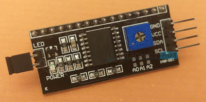
As the name suggests, the PCF8574 I2C LCD Module is a PCF8574 IC based module designed to convert regular 16×2 (or 20×4) character LCD Displays in to I2C based devices i.e., instead of using 8-bit or 4-bit parallel interface to send data, we can use I2C bus to send data to the display.
If you notice the board layout and pins of this I2C LCD Module, you can observe that it is a modified version of the regular IO Expander Module, which is also based on PCF8574 IC. This I2C LCD Module includes the POT to adjust the contrast of the LCD and pull-up resistors for SDA and SCL lines. So, you don’t need any additional connections.
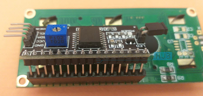
Just plugin the I2C LCD Module at the back of the 16×2 LCD and make connections between the microcontroller and the I2C LCD Module. That’s it.
ESP32 I2C LCD Interface
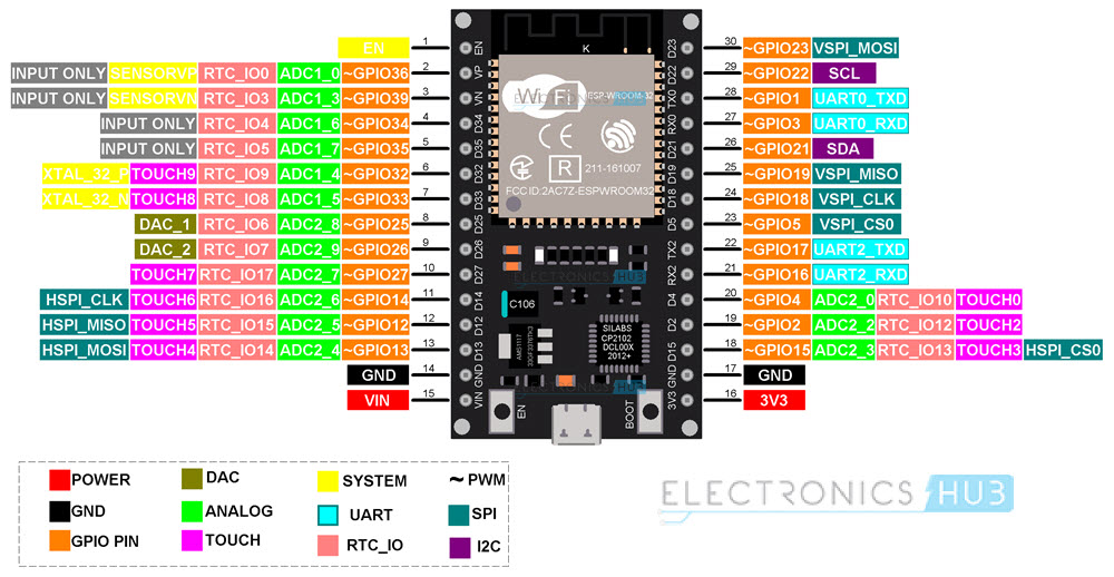
The first thing we need to figure out for ESP32 I2C LCD Interface to work is the I2C pins of ESP32. If you remember, in the ESP32 Pinout Tutorial, I mentioned that the ESP32 Microcontroller has two I2C interfaces and any GPIO pin can be configured to be used as an I2C Pin.
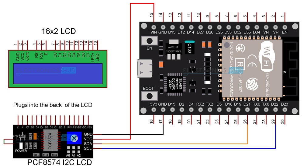
But after using all the GPIO pins for various purposes like SPI, UART, ADC etc., GPIO 22 and GPIO 21 are free (without any important alternative functions). So, in this project, we will be using GPIO 22 as SCL and GPIO 21 as SDA of the I2C interface. Another important point to note is that the 16×2 LCD runs on standard TTL voltage levels i.e., 4.7V to 5.3V. We cannot apply 3.3V as VCC to the I2C LCD Module even though the PCF8574 IC works at this voltage. So, keeping this in mind, the following table shows all the connections between I2C LCD Module and ESP32 As you can see from the table, the VCC of the I2C LCD Module is connected to VIN pin of the ESP32 Development Board. This is connected to USB Supply when ESP32 is powered through USB. So, we will get around 5V on this pin.
Components Required
ESP32 DevKit Development Board 16×2 Character LCD PCF8574 I2C LCD Module Breadboard Connecting Wires Micro-USB Cable
Circuit Diagram
The following image shows the circuit diagram for demonstrating ESP32 I2C LCD Interface.
Preparing Arduino IDE
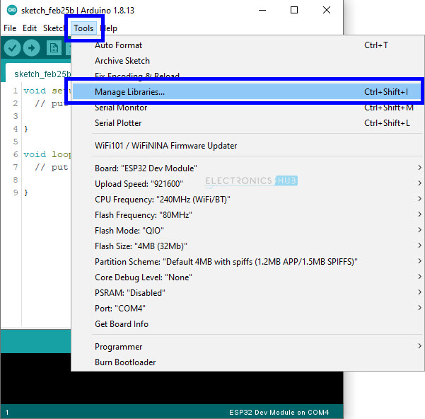
You have to download one library called ‘LiquidCrystal_I2C’ in order to work with I2C LCD Module. If you already installed this library, you can skip this step. If not, then follow along. Open Arduino IDE and open the library manager by selecting Tools -> Manage Libraries. . .
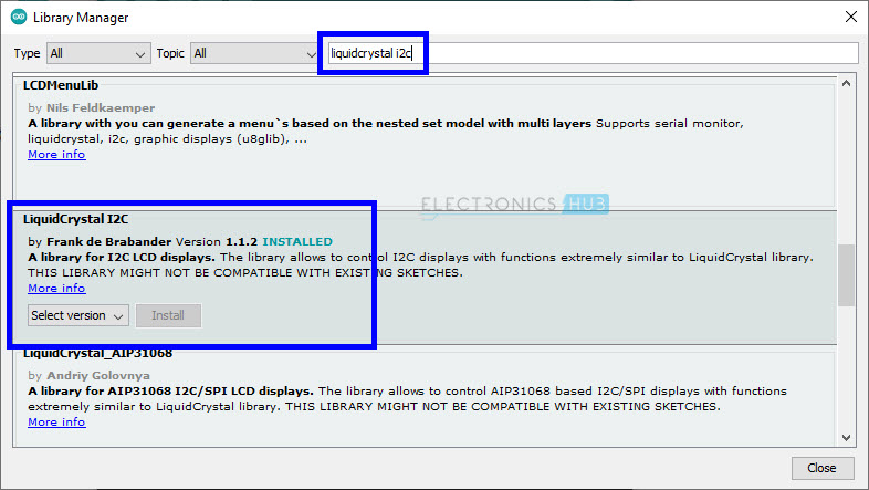
Once the library manager window opens, search for ‘liquidcrystal i2c’ and install the library ‘LiquidCrystal I2C’ by Frank de Brabander. There are other libraries for I2C LCD. You can try them as well.
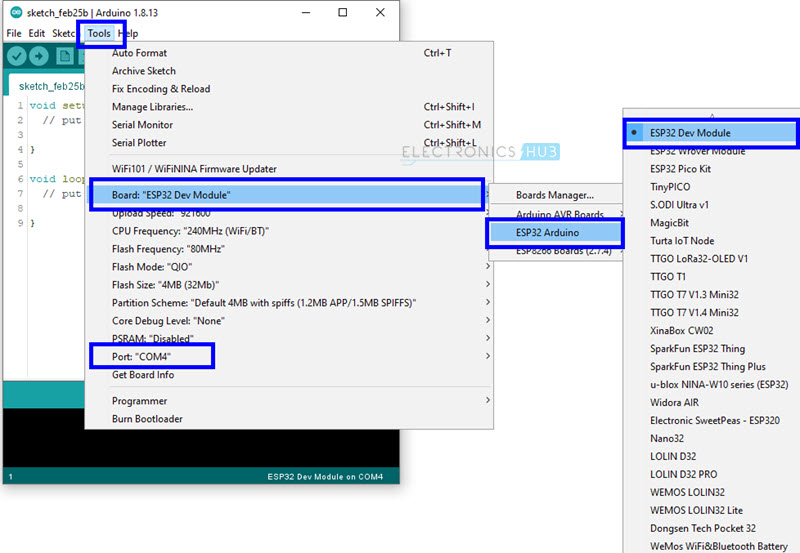
Close the library manager. Make all the necessary connections as per the circuit diagram and plug in the ESP32 board to the computer. In the Arduino IDE, select the correct board (ESP32 Dev Module) and also the correct COM Port.
Finding the Slave Address of I2C LCD Module
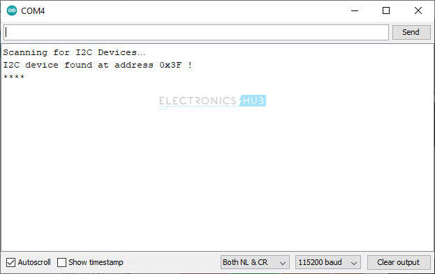
Since we are working with I2C interface, the slave address is one of the important things we need to be aware of. Here, the ESP32 Microcontroller is the master and the PCF8574 I2C LCD Module is the slave. You can refer to the datasheet of PCF8574 IC and calculate the slave address but for now we will go with the easy way i.e., a small program which determines the slave address automatically. In fact, we used the same code with Arduino and ESP8266 for other I2C related projects. After making all the necessary connections between ESP32 and I2C LCD Module, upload the following code and open the serial monitor of Arduino IDE.
As you can see from the screenshot of the serial monitor, the slave address of PCF8574 I2C LCD Module is 0x3F.
Displaying Simple Text
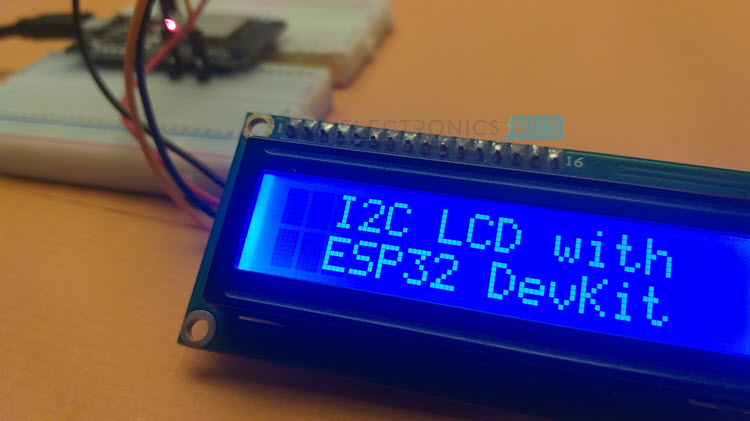
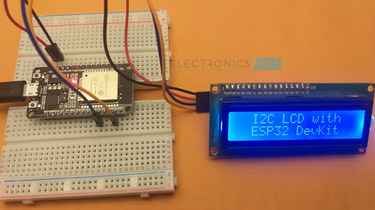
Let us use this slave address and display some basic text on the 16×2 LCD display using I2C LCD Module. Use the following code and see the output.
Code
Displaying ADC Result on LCD
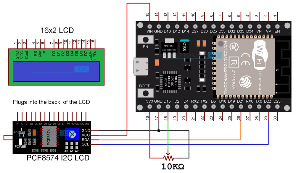
For the next code, let us make a small circuit involving a potentiometer and ADC of the ESP32. I connected a 10 KΩ POT to ADC 2 Channel 3 of ESP32. It is associated with GPIO 15 Pin (D15 on ESP32 DevKit Board). In the code, I configured GPIO 15 as Analog Input pin and the displayed the result of ADC on the LCD.
Circuit Diagram
The following image shows the circuit diagram for connecting 10 KΩ Potentiometer to ESP32 Development Board and displaying the result of ADC on the I2C LCD.
Code
Conclusion
A simple tutorial on interfacing PCF8574 I2C LCD Module with ESP32 Development Board. You learned the importance of I2C LCD Module, I2C pins on ESP32, how the ESP32 I2C LCD Interface works and how to display some text on the LCD. You can even display some special characters or make a scrolling text. Comment * Name * Email * Website
Δ




![]()