Hence, in this project, I will not only give the information of LCD and also provide the code in C language which is working fine without any errors.
A Brief Note on 16×2 LCD
16×2 Liquid Crystal Display which will display the 32 characters at a time in two rows (16 characters in one row). Each character in the display is of size 5×7 pixel matrix. This matrix differs for different 16×2 LCD modules, if you take JHD162A, this matrix goes to 5×8. There are 16 pins in the LCD module, the pin configuration us given below
PIN NONAMEFUNCTION 1VSSGround pin 2VCCPower supply pin of 5V 3VEEUsed for adjusting the contrast commonly attached to the potentiometer. 4RSRS is the register select pin used to write display data to the LCD (characters), this pin has to be high when writing the data to the LCD. During the initializing sequence and other commands this pin should low. 5R/WReading and writing data to the LCD for reading the data R/W pin should be high (R/W=1) to write the data to LCD R/W pin should be low (R/W=0) 6EEnable pin is for starting or enabling the module. A high to low pulse of about 450ns pulse is given to this pin. 7DB0 8DB1 9DB2 10DB3 11DB4DB0-DB7 Data pins for giving data(normal data like numbers characters or command data) which is meant to be displayed 12DB5 13DB6 14DB7 15LED+Back light of the LCD which should be connected to Vcc 16LED-Back light of LCD which should be connected to ground.
So by reading the above table you can get a brief idea how to display a character. For displaying a character you should enable the enable pin (pin 6) by giving a pulse of 450ns, after enabling the pin6 you should select the register select pin (pin4) in write mode. To select the register select pin in write mode you have to make this pin high (RS=1), after selecting the register select you have to configure the R/W to write mode that is R/W should be low (R/W=0).
Follow these simple steps for displaying a character or data
E=1; enable pin should be high RS=1; Register select should be high R/W=0; Read/Write pin should be low.
To send a command to the LCD just follows these steps:
E=1; enable pin should be high RS=0; Register select should be low R/W=0; Read/Write pin should be low.
Commands: There are some preset commands which will do a specific task in the LCD. These commands are very important for displaying data in LCD. The list of commands given below:
CommandFunction 0FFor switching on LCD, blinking the cursor. 1Clearing the screen 2Return home. 4Decrement cursor 6Increment cursor EDisplay on and also cursor on 80Force cursor to beginning of the first line C0Force cursor to beginning of second line 38Use two lines and 5x7 matrix 83Cursor line 1 position 3 3CActivate second line 0C3Jump to second line position 3 0C1Jump to second line position1
To get the detailed information, Click Here and Download the Datasheet
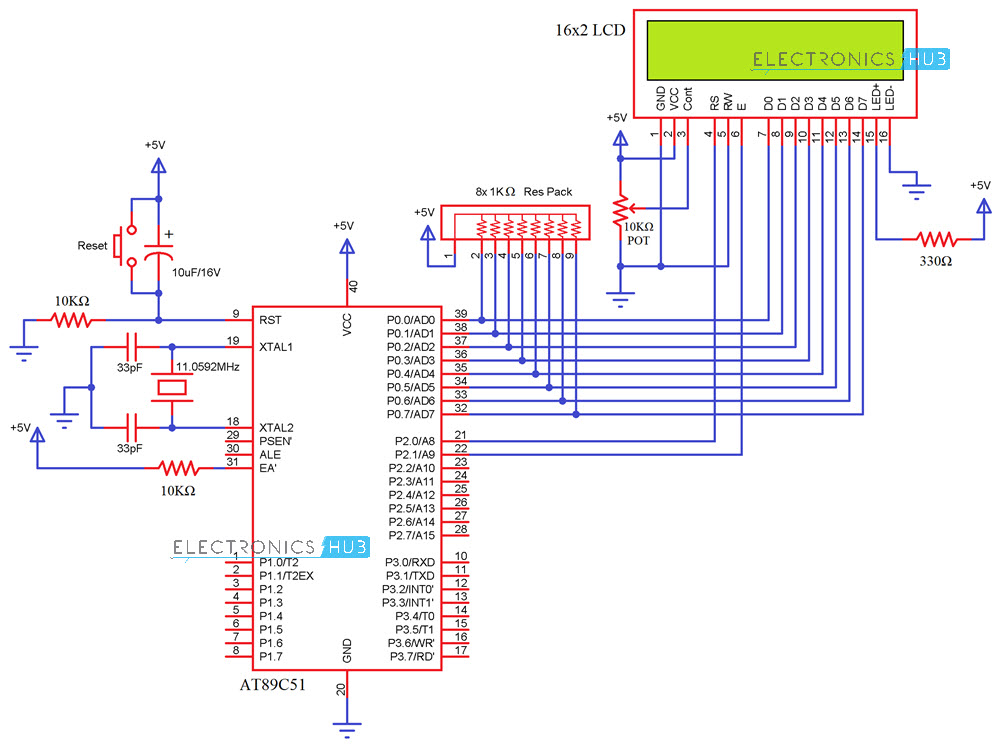
Interfacing 16×2 LCD with 8051 Circuit Diagram
Components Required
AT89C51 (8051 Microcontroller) 16X2 LCD Display 11.0592MHz Crystal 2 X 33pF Capacitors 2 X 10 KΩ Resistors 1 KΩ X 8 Resistor Pack 10 KΩ Potentiometer 330Ω Resistor Push Button 10μF/16V Capacitor 8051 Programmer 5V Power Supply Connecting Wires
Circuit Explanation
The crystal oscillator, along with two 33pF Capacitors, are connected to XTAL1 and XTAL2, which will provide the system clock to the microcontroller. RST Pin is pulled-LOW with the help of a 10KΩ Resistor. With the help of a 10μF Capacitor and a Push Button, you can reset the 8051 Microcontroller. EA is pulled-HIGH with the help of a 10KΩ resistor. The data pins of the LCD are connected to PORT0 (first, the PORT0 pins must be pulled-HIGH with the help of a 1KΩ Resistor Pack). RS and E are connected to PORT2 pins P2.0 and P2.1. A 10KΩ Potentiometer is used to adjust the contrast of the LCD.
Programming LCD to 8051
Coming to the programming you should follow these steps:
STEP1: Initialization of LCD. STEP2: Sending commands to LCD. STEP3: Writing the data to LCD.
[Also Read: How To Make an Adjustable Timer ]
Initializing LCD
To initialize LCD to the 8051 the following instruction and commands are to be embed in to the functions
0x38 is used for 8-bit data initialization. 0xoC for making LCD display on and cursor off. 0X01 for clearing the display of the LCD. 0x80 for positioning the cursor at first line .
Sending Commands to the LCD
E=1; enable pin should be high RS=0; Register select should be low for sending commands Placing the data on the data registers R/W=0; Read/Write pin should be low for writing the data.
Writing the Data to the LCD
E=1; enable pin should be high RS=1; Register select should be high for writing data Placing the data on the data registers R/W=0; Read/Write pin should be low for writing the data.
Code
Additional Codes
The programs given below will use above functions and display the complete string which is given by the programmer to display the data. We have provided two demo codes working properly and easy to understand.
Code 1
Code 2
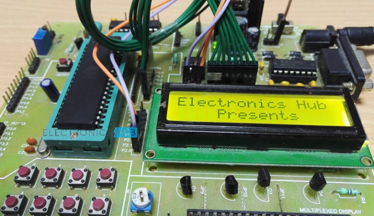
ORG 0000H HERE: MOV A,#38H ACALL CMND MOV A,#0FH ACALL CMND MOV A,#06H ACALL CMND MOV A,#01H ACALL CMND MOV A,#080H ACALL CMND MOV A,#’ ‘ ACALL DISP MOV A,#’H’ ACALL DISP MOV A,#’E’ ACALL DISP MOV A,#’L’ ACALL DISP MOV A,#’ L’ ACALL DISP MOV A,#’O’ ACALL DISP SJMP HERE CMND: MOV P2,A CLR P3.5 CLR P3.4 SETB P3.3 CLR P3.3 RET DISP: MOV P2,A SETB P3.5 CLR P3.4 CLR P3.3 SETB P3.3 RET END Comment * Name * Email * Website
Δ
![]()
![]()
![]()
![]()
![]()

