Circuit
WORKING
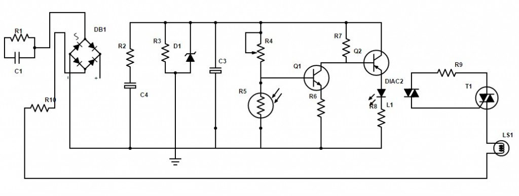
Instead of giving the AC supply directly to the bridge rectifier, we implement a tank circuit series with the bridge rectifier.
So what is the use of tank circuit here??? Here the tank circuit acts as a current limiting device. In simple, in AC circuit the resistance of the capacitor was calculated by Xc = 1/ 2piFC Where , F = frequency C = capacitance Pi = 3.14 unit of Xc is ohms for example frequency = 50 hz capacitance of the capacitor = 2.2uf Xc = 1 / (2 X 3.14 X 50 X (1000 x 10 e -6)) = 1447 ohms or 1.4 k ohms by using ohms law, V / R = I I = 230 / 1447 I = 0.15 —-> 150 mA From here we can find that, the current entering into the bridge rectifier was 150mA. In order to discharge the capacitor, we connected the R1 across the C1. From bridge the circuit closed by connecting to the neutral via 10ohms resistor,which acts as a fuse. The capacitor c2 connected in parallel with bridge output which acts as a filter to reduce the noise from the bridge o/p.
How to select the c2 ???? from the concepts of full wave rectifier we know that, Vmax = Vrms X 1.414 here, Vrms is the input voltage. Vmax = 230 X 1.414 = 325.22 volts. So maximum RMS voltage across the bridge rectifier was around 325 volts.The selection of the capacitor should be more than 350 Volts. In order to reduce the voltage from 320 to 10 volts across the circuit, we are using a 10v zener diode. It is important to use a current limiting resistor series with the zener to prevent the large current flow into it. using this formula, Rz = Vt – Vz / Iz where, Rz = resistance required Vt = total polariation resistance voltage Vz = zener voltage Iz = zener current Rz = (325 – 10) / 0.02 = 15750 ohms or 15.7Kohms Resistor in series with the zener diode should be 15 k ohms. But in some case the resistor will become very hot. So try to use 35 to 45 k ohms 5 watts resistor. Once we reduce the current we can connect the zener diode to reduce the voltage. The 10K resistor across the zener diode will support to handle the load. We find some noise in the circuit after regulating the voltage. In order to omit that we used the 2 more capacitor (c3 and c4 ) parallel with the circuit. The 100k variable pot in series with the LDR forms a voltage divider. By varying the pot value we can change the sensitivity of the LDR. LDR will have high resistance when there is no light around it. This helps to turn on the T1 (NPN). Once the T1 is ON, the voltage across the collector and emitter will become LOW. This makes the T2(PNP) to turn on.
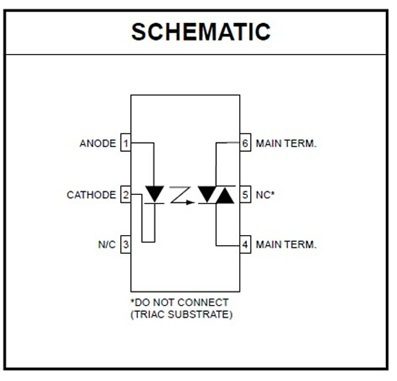
The high output of the T2 was connected to the 1 pin of the optocoupler, Internally the 1st pin was nothing but an anode of led. The cathode was the 2nd pin. In order to reduce the current across the internal led, the resistor R7 was connected. Once the internal led was turn on, the photo DIAC inside the optocoupler will conduct. In simple, current will flow from mains to 6th pin and comes out from the 4th pin. Which helps to turn on the TRIAC attached to it. When the circuit closed by the triac, the light will glow. Related Projects
Auto night Lamp Using High Power Leds Automatic Washroom Switch Automatic LED Emergency Light
Comment * Name * Email * Website
Δ
![]()
![]()
![]()
![]()
![]()

