The circuit is based on Zener diode’s voltage regulator operation. The circuit will provide a stable 4.7V at the output. There are some calculations to be performed to get desired current at the output. The following article is divided into circuit diagram, introduction to Zener regulators and working of the project.
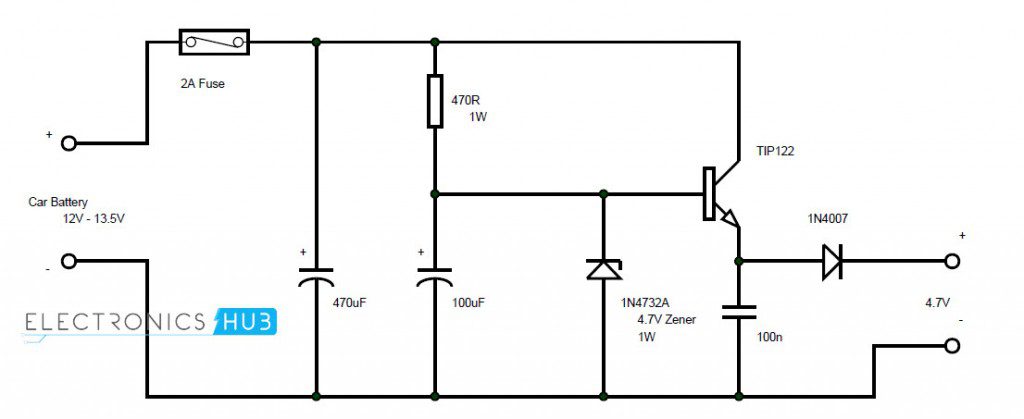
Circuit Diagram
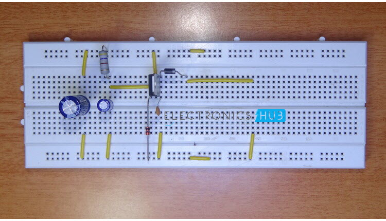
Components Required
TIP 122 — 1 1N4732A (4.7V – 1W Zener diode) — 1 1N4007 — 1 470Ω 1W — 1 470 µF — 1 100 µF — 1 100 nF — 1 2A Fuse — 1
Zener Diode Voltage Regulator
Under reverse bias condition, a Zener diode can be used as a simple voltage regulator. A simple Zener diode based voltage regulator consists of a Zener diode with a current limiting resistor is series. When the input voltage increases, the current through the Zener diode will increase but the voltage across it will be constant. As the current in the circuit is increasing and the voltage across the Zener is constant, the voltage across the resistor, which is known as Zener resistor, will increase. Hence, selection of Zener diode’s power rating, value of Zener resistor and power rating of resistor will depend on the desired output current.
Circuit Design of Car DC Adapter Circuit
The input voltage for the circuit is taken from the car battery. Different car batteries have different ratings or capacity. Hence, a 2A fuse is used to restrict the maximum current flow in the circuit. This supply is given to collector of TIP122 transistor. It is also given to cathode of Zener diode via Zener resistor. A diode is connected at the emitter of the transistor to get the output.
Working of Car DC Adapter
The aim of this project is to build a simple DC adapter to charge mobile phones using car battery. All the connections are made as per the circuit diagram. The working of this circuit along with necessary calculations are explained below. The output voltage from a car battery can be in the range of 12V to 13.5V. The fuse will restrict the maximum load current to 2A. The Zener diode used in the circuit is 1N4732A which has a reverse breakdown voltage of 4.7V. Hence, the voltage across the Zener will be a constant 4.7V. As this is connected to base of TIP122 transistor, it will be always on and the output will be a stable 4.7V. The current in the above circuit is very less (around 15mA). This is not sufficient to charge a mobile phones battery. In order to increase the current of the circuit, it is important to calculate the Zener resistor, power rating of the resistor and power rating of Zener diode. So, a simple calculation is made by assuming certain values. We know the input is 12V and the output voltage is 4.7 V (output voltage is nothing but the Zener breakdown voltage). If the output current we desire is 300mA, then the current in the circuit should be around 330mA (300mA + 10% for rest of the circuit). Now the Zener resistance can be calculated as Zr = (12V – 4.7V) / 330mA = 22.1Ω. Hence, a 22Ω Zener resistor must be chosen. Now for power rating of Zener diode, we know that the breakdown voltage of Zener diode is 4.7V and the maximum current in the circuit is 330mA. The power rating of Zener diode is calculated as breakdown voltage multiplied by maximum current. Zener diode power rating = 4.7V * 330 mA = 1.55W. Hence, it is safe to use a 2W Zener diode. As the current in the circuit is increased, the voltage drop across the resistor will increase. The power rating of the resistor is also very important. If the supply voltage is 12V and the breakdown voltage of Zener diode is 4.7V, the voltage drop across the resistor is approximately 7.3V. The assumed maximum current in the circuit is 330mA. So, the power rating of the resistor can be calculated as Zener resistor power rating = 7.3V * 330mA = 2.4W. Hence, a 3W resistor must be selected. NOTE
A simple DC adapter using car battery as supply is designed here. It can be used to charge mobile phones. Proper calculations must be made before selecting the components and their ratings. The best application of Zener based regulators is to get a stable voltage from an unreliable source like renewable energy based power banks.
Comment * Name * Email * Website
Δ
![]()
![]()
![]()
![]()
![]()

