These modified inverters produce a square wave and these are not used to power delicate electronic equipments . Here, a simple voltage driven inverter circuit using power transistors as switching devices is build, which converts 12V DC signal to single phase 220V AC.
Principle Behind this Circuit
The basic idea behind every inverter circuit is to produce oscillations using the given DC and apply these oscillations across the primary of the transformer by amplifying the current. This primary voltage is then stepped up to a higher voltage depending upon the number of turns in primary and secondary coils. Also get an idea about 12V to 24V DC Converter Circuit
Inverter circuit Using Transistors
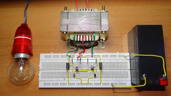
A 12V DC to 220 V AC converter can also be designed using simple transistors. It can be used to power lamps up to 35W but can be made to drive more powerful loads by adding more MOSFETS. The inverter implemented in this circuit is a square wave inverter and works with devices that do not require pure sine wave AC.
Circuit Diagram
Components required
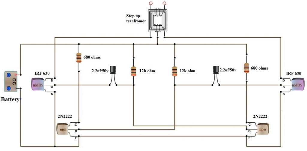
12v Battery MOSFET IRF 630 -2 2N2222 Transistors 2.2uf capacitors-2 Resistor 680 ohm-2 12k-2 12v-220v center tapped step up transformer.
2N2222 Datasheet IRF630 Datasheet
Working
The circuit can be divided into three parts: oscillator, amplifier and transformer. A 50Hz oscillator is required as the frequency of AC supply is 50Hz. This can be achieved by constructing an Astable multivibrator which produces a square wave at 50Hz. In the circuit, R1, R2, R3, R4, C1, C2, T2 and T3 form the oscillator. Each transistor produces inverting square waves. The values of R1, R2 and C1 (R4, R3 and C2 are identical) will decide the frequency. The formula for the frequency of square wave generated by the astable multivibrator is F = 1/(1.38R2C1) The inverting signals from the oscillator are amplified by the Power MOSFETS T1 and T4. These amplified signals are given to the step-up transformer with its center tap connected to 12V DC.
Output Video
By using a 24V battery, loads up to 85W can be powered, but the design is inefficient. In order to increase the capacity of the inverter, the number of MOSFETS must be increased. To design a 100 watt Inverter read Simple 100 Watt inverter
12v DC to 220v AC Converter Circuit Using Astable Multivibrator
Inverter circuits can either use thyristors as switching devices or transistors. Normally for low and medium power applications, power transistors are used. The reason for using power transistor is they have very low output impedance, allowing maximum current to flow at the output. One of the important applications of a transistor is in switching. For this application, the transistor is biased in saturation and cut-off region. When the transistor is biased in saturation region, both the collector emitter and collector base junctions are forward biased. Here the collector emitter voltage is minimum and collector current is maximum. Another important aspect of this circuit is the oscillator. An important use of 555 Timer IC is in its use as an astable multivibrator. An astable multivibrator produces an output signal which switches between the two states and hence can be used as an oscillator. The frequency of oscillation is determined by the values of capacitor and resistors. [Also Read: How To Make an Adjustable Timer ] Circuit Diagram Circuit Components
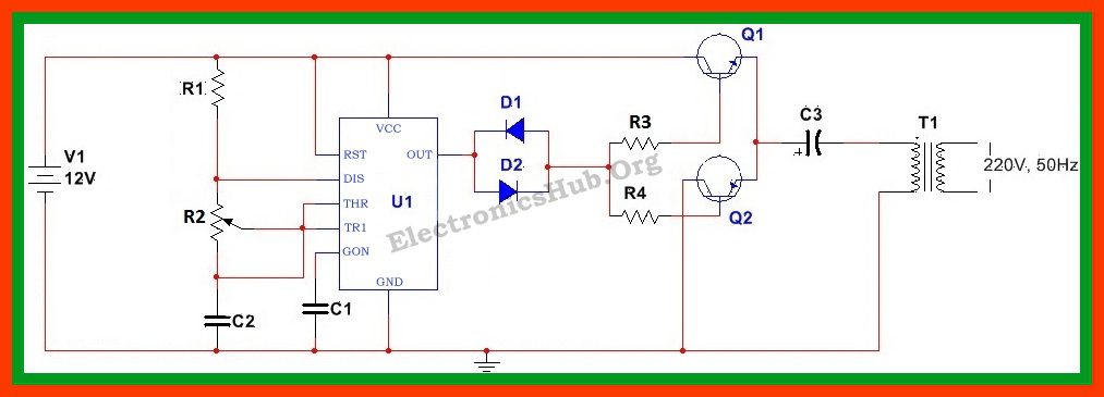
V1 = 12V R1 = 10K R2 = 150K R3 = 10Ohms R4 = 10Ohms Q1 = TIP41 Q2 = TIP42 D1 = D2 = 1N4007 C3 = 2200uF T1 = 12V/220V step up transformer
Circuit Design Explanation
Oscillator Design:An astable multivibrator can be used as an oscillator. Here an astable multivibrator using 555 timer is designed. We know, frequency of oscillations for a 555 timer in astable mode is given by: f = 1.44/(R1+2*R2)C where R1 is the resistance between discharge pin and Vcc, R2 is the resistance between discharge pin and threshold pin and C is capacitance between threshold pin and ground. Also the duty cycle of the output signal is given by: D = (R1+R2)/(R1+2R2) Since our requirement is f =50Hz and D = 50% and assuming C to be 0.1uF, we can calculate the values of R1 and R2 to be 10K and 140K Ohms respectively. Here we prefer using a 150K potentiometer to fine tune the output signal. Also a ceramic capacitor of 0.01uF is used between the control pin and ground. Switching Circuit Design:Our main aim is to develop an AC signal of 220V. This requires use of high power transistors to allow the flow of maximum amount of current to the load. For this reason we use a power transistor TIP41 with a maximum collector current of 6A, where the base current is given by the collector current divided by the DC current gain. This gives a bias current of about 0.4A *10, i.e.4A. However since this current is more than the maximum base current of the transistor, we prefer a value less than the maximum base current. Let us assume the bias current to be 1A. The bias resistor is then given by Rb = (Vcc – VBE(ON))/Ibias For each transistor, the VBE(ON) is about 2V. Thus Rb for each is calculated to be 10 Ohms. Since the diodes are used for biasing, the forward voltage drop across the diodes should be equal to the forward voltage drops across the transistors. For this reason, diodes 1N4007 are used. The design considerations for both the PNP and NPN transistors are same. We are using a PNP power transistor TIP42. Output Load Design: Since the output from the switching circuit is a pulse width modulated output, it might contain harmonic frequencies other than the fundamental AC frequency. For this reason, an electrolyte capacitor needs to be used to allow only the fundamental frequency to pass through it. Here we use an electrolyte capacitor of 2200uF, large enough to filter out the harmonics. Since it is required to get 220V output, it is preferred to use a step up transformer. Here a 12V/220V step up transformer is used.
12v DC to 220v AC Converter Circuit Operation
When this device is powered using the 12V battery, the 555 timer connected in astable mode produces square wave signal of 50Hz frequency. When the output is at logic high level, diode D2 will conduct and the current will pass through diode D1, R3 to the base of transistor Q1. Thus transistor Q1 will be switched on. When the output is at logic low level, diode D1 will conduct and current will flow via and D1 and R4 to the base of Q2, causing it to be switched on. This allows the DC voltage to be produced across the primary of the transformer at alternate intervals. The capacitor ensures that the frequency of the signal is at the required fundamental frequency. This 12V AC signal across the primary of the transformer is then stepped up to 220V AC signal across the transformer secondary.
Applications of 12v DC to 220v AC Converter Circuit
Limitations
Note Instead of 555 timer one can use any astable multivibrator. For example this circuits can also be build using 4047 astable multivibrator,whose output current is amplified and applied to the transformer. [Read: Solar Inverter for Home] Can any one help me please where might the problem could be ? may i know how much the Amper-Hour (Ah) of the battery? It is possible to produce exact sine wave Thank You Comment * Name * Email * Website
Δ
![]()
![]()
![]()

![]()
![]()

