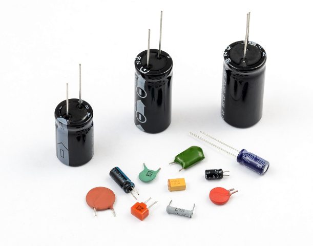
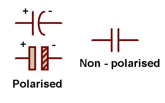
Generally, a capacitor has two parallel metal plates which are not connected to each other. The two plates in the capacitor are separated by non conducting medium (insulating medium) this medium is commonly known as Dielectric. There are different types and different shapes of capacitors available , from very small capacitors which are used in resonance circuits to large capacitors for stabilising HVDC lines. But all capacitors are doing the same work that is storing the electrical charge. The shape of a capacitor is rectangular, square, circular, cylindrical or spherical shape. Unlike a resistor, an ideal capacitor does not dissipate energy.As the different types of capacitors are available different symbols were available to represent them which are shown below.
Why capacitors are important?
Capacitors have many properties like Likewise, capacitors exhibit many properties , when used in AC or DC circuits and hence they play important role in electrical and electronic circuits.
Construction of a Capacitor
As said before , there are different types of capacitors. These different types will have different type of construction. A Parallel plate capacitor is the simplest capacitor. Let us understand the construction of this capacitor. It consists of two metal plate separated by a distance. The space between these two plates is filled with a dielectric material. The two leads of the capacitor are taken from these two plates. The capacitance of the capacitor depends on the distance between the plates and area of the plates. Capacitance value can be changed by varying any of these parameters. A variable capacitor can be constructed by making one of these plates fixed and other moving.
Dielectric Of a Capacitor
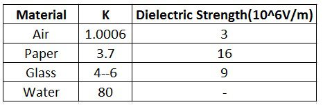
Dielectric acts as an insulating material between the plates . Dielectric can be any non conducting material such as ceramic, waxed paper, mica, plastic or some form of a liquid gel. Dielectric also plays an important in deciding the value of capacitance. As the dielectric is introduced between the plates of the capacitor ,its value increases. Different dielectric materials will have different dielectric constants ,however this value is >1. Below table gives value of dielectric constant for each dielectric material
Dielectric can be of two types The product of the relative permittivity (εr) of the dielectric material and permittivity of free space (εo) is known as “Complex permittivity” or “Actual permittivity” of the dielectric material. The expression for the complex permittivity is given as follows, ε = ε0 * εr The value of complex permittivity will always be equal to the relative permittivity, because the permittivity of free space is equal to ‘one’. The value of dielectric constant or complex permittivity varies from one dielectric material to another. Some standard values of complex permittivity (ε) for common dielectric materials are Air = 1.0005, Pure Vacuum = 1.0000, Mica = 5 to 7, Paper = 2.5 to 3.5, Wood = 3 to 8, Glass = 3 to 10 and Metal Oxide Powders = 6 to 20 and etc. capacitors can be classified according to the properties and characteristics of their insulating or dielectric material, they are given below as
Working
As said before capacitor consists of two conductor separated by a dielectric , when there is any potential difference between the two conductors electric potential is developed.This causes the capacitor to charge and discharge. Let us understand this in a practical way. When the capacitor is connected to a battery(a DC source) , current starts flowing through the circuit . Thus negative charge is accumulated on one plate and positive charge is accumulated on the other plate. This process continuous until the capacitor voltage reaches supply voltage. When the charging voltage is equal to the supply voltage capacitor stops charging further even though the battery is connected. When the battery is removed two plates will be accumulated with positive and negative charges. Thus the charge is stored in the capacitor. But when the supply voltage is from an AC source it charges and discharges continuously .The rate of charging and discharging depends on the frequency of the source.
Example
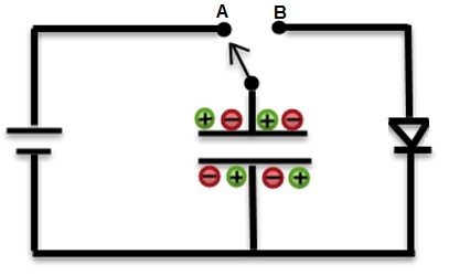
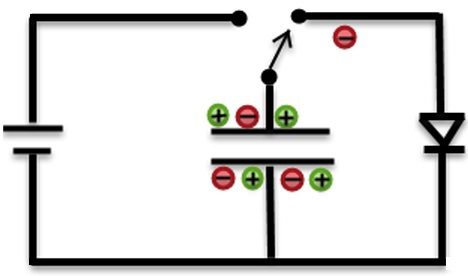
Working can be understood using simple example here. Below circuit shows two switches A and B. When switch 1 is closed , current starts flowing from from the battery to the capacitor. When the capacitor voltage reaches the supply voltage ,it stops charging further.
Now connect the switch to position B. Now you can observe the LED starts glowing and this slowly fades out as the capacitor is discharging.
Capacitance of the capacitor is given by C=KεA/d or C= εA/4πd or C = εo * εr (A/d) Where, C – Capacitance of the capacitor A – Area between the plates D – Distance between the two Plates εo – Permittivity of free space εr – Relative permittivity. K- Dielectric Constant
Capacitance of a Capacitor
Capacitance is the property of the capacitor that defines the maximum amount of electrical charge stored in it.it exists in nature everywhere. Capacitance may vary depending on the shape of the capacitor. Capacitance can be calculated by using the geometry of the conductors and dielectric material properties. Let us see the capacitance of a parallel plate capacitor. Capacitance is defined as the ratio of charge (Q) on the either plates to the potential difference(V) between them , C =Q/V, Thus current can be obtained as I(t)=C[d(v)/d(t)] This can can be expressed Farads (F) which is named after English physicist Michael Faraday. From the above definition we can observe that capacitance is directly proportional to the charge (Q) and is inversely proportional to the voltage (V). Capacitance of the capacitor can be increased by increasing the number of plates, which helps to maintain the same size of the capacitor. Here, area of the plates is increased.
Standard units of capacitance
Generally Farads is a high value so, capacitance is expressed as sub units of capacitor real time such as as micro farads(uF) , nano farads(nF) and pico farads(PF). Most of the electrical and electronic applications are covered by the following standard unit (SI) prefixes for easy calculations,
1 mF (milli farad) = 10−3 F = 1000 μF = 1000000 nF 1 μF (microfarad) =10−6 F = 1000 nF = 1000000 pF 1 nF (nano farad) = 10−9 F = 1000 pF 1 pF (picofarad) = 10−12 F
To convert µF to nF or pF or to a wide range of other units and vice versa, we need to use the Electric Capacitance Unit Converter.
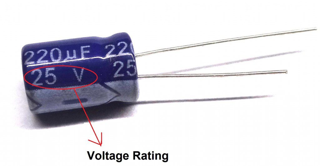
Voltage Rating of a Capacitor
This is not voltage until which the capacitor charges but the maximum voltage until which the capacitor can operate safely. This voltage is called as working voltage (WV) or DC working voltage (DC-WV).Below figure shows the voltage rating of the capacitor.
If the capacitor is applied with voltage greater than this voltage, it may be damaged by producing an arc between the plates due to dielectric break down. While designing the circuits with capacitors, care should be taken such that the voltage rating of the capacitor is greater than the voltage used in the circuit. For example if the circuit operating voltage is 12V then it is necessary to choose a capacitor with voltage rating of 12V or above. This working voltage of a capacitor depends on the factors like dielectric material used between the capacitor plates, dielectric thickness and also on the type of circuit which is used. Thank you Ralph Comment * Name * Email * Website
Δ
![]()
![]()
![]()
![]()
![]()

