With the advancement of electrical drives for traction systems, this electrification of traction becomes much popular in several traction services including metro or suburban railways.
What is Electric Traction System?
A system which causes the propulsion of vehicle in which tractive or driving force is obtained from various devices such as diesel engine drives, steam engine drives, electric motors, etc. is called as traction system. It can also be defined as the railway vehicle that provides the necessary traction power to move the train is referred as the traction or locomotive. This traction power can be diesel, steam or electric power. The traction system can be classified as non-electric and electric traction systems.
Non-electric traction system
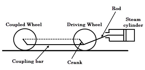
A traction system that doesn’t use electrical energy for the movement of vehicle at any stage is referred as non-electric traction system. The steam engine drive is the best example of a non electric traction system and it is the first locomotive system used before the invention of actual electric traction systems. The steam locomotive system uses the superheated steam to produce mechanical energy for the movement of vehicle.
This may use coal or petroleum as fuel, liberates thermal energy to produce the steam pressure and then it is converted into kinetic energy so that mechanical movement of the vehicle is produced.
The disadvantages of steam locomotive systems , such as , low fuel efficiency, poor technical performance, maintenance of a large number of water supply facilities, and high maintenance cost makes them to be replaced by alternative traction systems and hence the electric traction. The following are the two types of non electric traction systems.
Steam engine drive based vehicles (used for railways) Internal combustion (IC) engine drive based vehicles (used for road transport)
Electric traction system
Electric traction involves the use of electricity at some stage or all the stages of locomotive movement. This system includes straight electrical drive, diesel electric drive and battery operated electric drive vehicles. In this, electrical motors are used for producing the vehicle movement and are powered by drawing electricity from utilities or diesel generators or batteries. It has many advantages over non-electric traction systems such as more clean and easy to handle, no need of coal and water, easy speed control, high efficiency, low maintenance and running costs, etc. As mentioned above, electric traction systems can be self contained locomotives or vehicles that receive power from electric distribution system (substations). Self contained locomotives includes
Battery operated electrical drives Diesel operated electrical drives
Vehicles that receives the power from substation is also referred as a third rail systems which includes
Railway electric vehicles fed from overhead AC or DC supply Trolley buses or tramways supplied with DC supply (i.e., battery electric drives)
4 Supply Systems of Electric Traction
The way of giving the power supply to locomotive unit is generally referred as traction electrification system. Presently, there are four types of track electrification systems are available based on the availability of supply. These are
DC traction system Single phase AC traction system Three phase AC traction system Composite traction system
DC Traction System
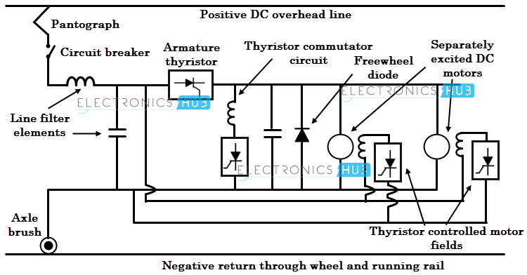
In this traction system, electrical motors are operates on DC supply to produce necessary movement of the vehicle. Mostly DC series motors are used in this system. For trolley buses and tramways, DC compound motors are used where regenerative braking is required. The various operating voltages of DC traction system include 600V, 750 V, 1500V and 3000V.
DC supply at 600-750V is universally employed for tramways and light metros in urban areas and for many suburban areas. This supply is obtained from a third rail or conductor rail, which involves very large currents. DC supply at 1500- 3000 is used for main line services such as light and heavy metros. This supply is drawn mostly from an overhead line system that involves small currents.
In both cases, only one conductor or rail is required to supply power to locomotive while track rails are used as return conductors in majority of cases. Both these supply voltages are fed from substations which are located 3-5 KM for suburban services and 40 to 50KMs for main line services. These substations receive power (typically, 110/132 KV, 3 phase) from electric power grids. This three phase high voltage is stepped-down and converted into single phase low voltage using scott-connected three phase transformers. This single phase low voltage is then converted into DC voltage using suitable converters or rectifier such as power electronic converter, rotary converters, mercury arc converters, etc. The DC supply is then applied to the DC motor via suitable contact system and additional circuitry.
The advantages of this system include
In case of heavy trains that require frequent and rapid accelerations, DC traction motors are better choice as compared AC motors. DC train consumes less energy compared to AC unit for operating same service conditions. The equipment in DC traction system is less costly, lighter and more efficient than AC traction system. It causes no electrical interference with nearby communication lines.
Despite all these advantages, DC electrical system necessitates AC to DC conversion substations relatively at very short distances. This is the main disadvantage of DC traction system. That’s why this system is preferred only for suburban and road transport services wherein stops are frequent and also distance between stops is small.
Single Phase AC Traction System
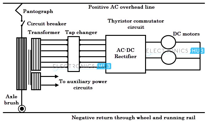
In this type of traction system, AC series motors are used to produce the propulsion of vehicle. This system uses AC voltages from 15-25KV at a frequency of 16.7 (i.e., 16 2/3) or 25 Hz. This low frequency leads to give better performance and more efficient operation by the series motor. This single phase supply is fed to the locomotive unit via a single overhead line while track provides the return path. The high voltages (15-25KV) obtained from overhead conductor are stepped down to a suitable motor operating range (typically 300-400V range) using step-down transformer carried by the locomotive unit itself. The secondary tapping of this transformer offer variable voltage to AC series motor for speed regulation. The low frequency operation of overhead line reduces the communication interferences. Also, the reactance of the line is low at lower frequency and hence the voltage drop in the line is reduced. Because of this low line voltage drop, it is feasible to locate the substations at 50 to 80kms apart from each other. Therefore, this system is preferred for main line services where cost of overhead system is not a much important factor and for suburban services where rapid acceleration and retardation are not required.
Three Phase AC Traction System
In this, three phase induction motors are used for the movement of locomotive. This system normally works on 3000-3600V AC at a frequency either 16 2/3 or normal supply frequency. This system employs two overhead lines for two phases, whereas the track forms third phase. These conductors are powered from substations which are rated at higher voltages and they receive power from three-phase transmission lines. The high voltages from transmission lines are stepped down to 3.3 KV (3000-3600 V) by transformers while the frequency is reduced by frequency converters installed at substations. The three phase induction motor used in this system has the following characteristics; simple and robust construction, provision of regenerative braking without additional equipment and high operating efficiency, better performance, etc. However, these motors are suffer with some drawbacks such as high starting current, low starting torque, complicated overhead structure, especially at crossings and junctions and not suitable constant speed characteristics of induction motor traction work. These systems are adopted where high output power is required and also where automatic regeneration braking is needed. However, these systems do not found much favour compared to other systems.
Composite Traction System
The above discussed methods have their own merits and demerits. Single phase AC system has less distribution cost whereas DC system has excellent driving capability by DC series motors and three phase system has automatic regenerative braking capacity. So by combining the advantages of AC/DC and single/three phase systems, the overall performance of the traction system gives better result than individual system and hence the evolution of composite system. Basically composite systems are of two types, namely
Single phase to three phase system Single phase to DC system
This traction system is also called Kando system. It consists of single phase16KV, 50 Hz supply which is fed from the substation and is being carried through a single overhead conductor. The single phase supply is then converted into three phase supply of the same frequency using phase converter equipment in the locomotive itself. The three phase supply is then fed to induction motors to drive the locomotive.
It is also possible to develop high starting torque of induction motors by reducing the supply frequency at ½ to 9 Hz by means of inverter controlled through silicon controlled rectifiers. The main advantage of this system is that the overhead two conductor arrangement of three phase AC system is reduced to a single overhead conductor and hence more economical. This traction system is most popular and widely used system everywhere. It combines the single phase high voltage AC distribution at industrial frequency with DC series motor traction. In this, the overhead line carries single phase, 25KV, 50 Hz supply which is then stepped down to a desired range using step-down transformer located in the locomotive unit itself.
This single phase supply is then converted into DC using rectifier (in the locomotive) and then applied to DC series motor. The advantages of this system include higher starting efficiency, less number of substations, simple substation design and lower cost of fixed installations.
Main Parts of AC Electric Locomotive
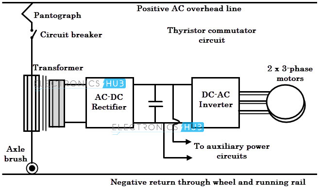
The figure below shows the block diagram of an AC locomotive system that employs single phase supply to drive three phase motor. The various components of this system include overhead contact wire, circuit breakers, pantograph, transformer, three phase traction motor, rectifier, inverter, smoothing reactor, etc.
Pantograph
The main function of pantograph is to maintain link between overhead conductor and power circuit of locomotive at different speeds of the vehicle under all wind conditions. It collects the current from overhead conductor and supplies to rest circuit.
Circuit Breaker
It protects the power circuit in the event of any fault by isolating it from the supply. It also isolates the circuit during maintenance.
Transformer
It receives the high voltage from overhead conductor via pantograph and circuit breaker and then step-down the voltage to desired level required by the rest circuit.
Rectifier
It converts a low voltage AC supply from the secondary of transformer to a DC supply.
DC Link
It connects the rectifier and inverter circuits. It consists of filter arrangement (capacitor and inductor arrangement) that filters the output from rectifier (by removing the harmonics form it) and then supplies it to the inverter.
Main Inverter
It converts the DC power to three phase AC power in order to drive three phase AC motors.
Axle Brush
It acts as a return path for the supply. Once the power is drawn to the locomotive from overhead system, the current complete its path through axle brush and one of running tacks.
Auxiliary Inverter
This inverter supplies the power to other parts in the locomotive unit including fans, motor blowers, compressors, etc.
Battery
It supplies the necessary starting current and also power up the essential circuits such as emergency lighting.
Compressor
It maintains the cooling/heating requirement in the locomotive unit.
Cooling Fans
These fans maintain the necessary cooling for the power circuits. Modern locomotive systems use electronically controlled air management systems to keep the desired temperature. Image Contributors Comment * Name * Email * Website
Δ


![]()