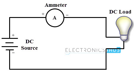
This implies that an ammeter must be connected in the path of the current flow where the current is being measured. These meters can be panel mountable or portable meters. In this article we are going to deal with portable ammeter which is a part of the multimeter.
Current Measurement using Multimeter
Both AC and DC currents can be measured with a multimeter by connecting the meter in series with the circuit, in which the current is measured provided the current in that circuit is limited or controlled by a load or appropriate values of resistance. It is to be noted that ammeter is a low resistance device and typically the impedance is less than 0.1 ohm. If the meter is connected in parallel to the supply unknowingly, this low resistance only limits the current flow through the meter.
Suppose this meter with 0.1 ohms resistance is connected across the 240 supply, the current flow would be around 2400 Amps (240/0.1 = 2400 A). This high current will lead to the destruction of ammeter. Thus, ammeter must be connected in series or in line with circuit in which current being measured. That’s why ammeters also referred as in-line ammeters.
Current Measurement using Analog Multimeter
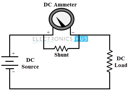
The working of the analog ammeter is same as that of PMMC meter. In this, a resistor is placed across the meter movement called as shunt which limits the amount of current passes through the meter. Since the meter movement is connected in parallel with shunt, the voltage applied across the meter is the voltage drop of the shunt. Thus, meter will give a full scale reading when the rated current flows through the shunt as shown in figure below. And hence the value of the shunt will vary depending on the desired full scale reading of the ammeter.
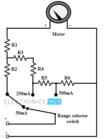
Many ammeters or multimeters are designed to operate at more than one range, i.e., it allows multiple scales in one meter. This can be achieved by connecting different shunts across the meter. A rotary switch in series with these shunt resistors connects desired shunt across the meter depending on the range being measured as shown in the figure. Again the values of these shunts are calculated depending on the full scale reading of the range (similar to that of single shunt meters).
For AC current measurements, analog multimeter consists of diode rectifier circuit that converts AC to corresponding DC current. However, this diode has certain turn ON voltage which affects the low current measurements (due to misrepresentation at low voltage side scale deflection). This is one of the reasons to have restricted ranges of AC currents in analog multimeters while some meters may not measure AC currents. Before measuring the current using multimeter, one should consider the following
Procedure to Measure DC Current using Analog Multimeter
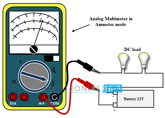
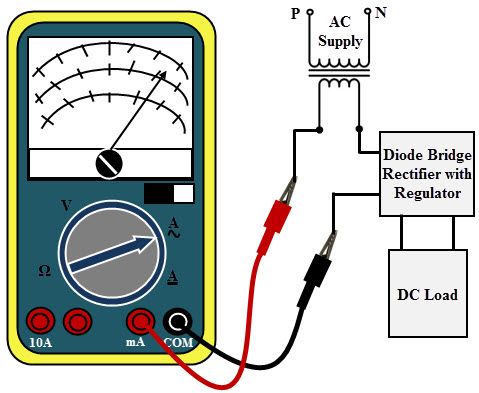
Insert red and black probes to the multimeter in their respective slots, depending on very high or very low current measurements. Some meters ‘mA’ symbol slot indicates low current measurements and ‘A’ symbol slot indicates high current measurements. Some meters, current values are directly printed on their respective slots. The red probe must be inserted into these slots while ‘COM’ symbol slot is the negative (or black) probe slot. Set range selector switch to DC measurement type of current and also select the expected range. It is always better to ensure maximum range for the measurement than that of anticipated because we can also reduce the range later if necessary. This avoids the unnecessary overload that could damage the meter. Switch off the power supply to the circuit in which the current being measured. And break the circuit so as to connect the meter in-series to the current path provided load is connected to that circuit. Connect the red probe to the positive side (source) of the terminal and back probe to the other side (load side or the end which is separated from the positive side) of the terminal. The meter will give a negative deflection if the probes are connected in reverse manner. Turn ON the power supply and optimize the range of multimeter by reducing the selector switch steps for the maximum deflection of the pointer. Always remember to change the position of the probes once the current reading is completed. And also turn the selector switch to maximum voltage position. This would reduce the chances of accidentally connecting meter next time across the load while multimeter is in ammeter mode. And hence the damage to the meter is avoided.
Procedure to Measure AC Current using Analog Multimeter
Measuring the AC current is similar to measuring DC current as stated above. There is not much difference between measuring AC and DC current; however, some of the necessary steps to take the AC measurements are given below.
Insert red probe in mA or A slot depending on the range of AC current being measured. Insert black probes into COM slot. Set range selector switch to AC form of current and select maximum range for the current measurement. Switch off the power supply to the circuit and make sure to separate the path of current (i.e., phase of the circuit) at which current to be measured in order to connect the meter in-line with circuit. Connect the red probe to the source side of the phase terminal and back probe to the other side of the phase terminal. Turn ON the power supply and optimize the range of multimeter by reducing the selector switch steps for the maximum deflection of the pointer.
Analog meters are provided with adjustment screw to set the needle position to zero. So make sure that the needle must be at zero position when reading is about to measure. If not, adjust accordingly.
Current Measurement using Digital Multimeter
Digital multimeters are widely used portable measuring instrument which has the advanced features than analog meters such as auto polarity, auto zeroing, auto ranging and automatic shut off. This multimeter is connected in-line with the wire or component by breaking circuit a part to measure the current. Most of DMMs have multiple ports for different range of current measurements. To measure the current (AC or DC) with a DMM, the internal circuit first converts the current at the input to a voltage in order to use by the ADC. This is carried by a series of switched resistors also called as shunts. According to the Ohm’s law, these shunts define the voltages proportional to input currents to be measured. AC current is measured in same method as shunts except that voltage across the shunt is directed towards AC to DC rectifier circuit before passing it to ADC.
DC/AC Current Measurement using Digital Multimeter
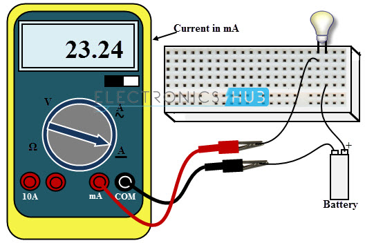
Connect the negative probe lead (black color probe) to the COM jack and the positive probe lead (red color probe) to either very low (mA or µA) or very high current range (A) jack depending on the higher range of the current being measured. Suppose if meter consists of 200mA and 10 A jacks, connect the red probe to 200mA jack for the maximum of 200mA current measurement, on the other hand connect red probe to 10 A jack for maximum of 10A current measurement. Set the type of current AC or DC. Set the range selector switch at the desired range that gives most sensitivity or simply select a high range so that later we can decrement the steps if necessary (Some DMMs are of auto range meters so no need for setting the range). Turn OFF the circuit and interrupt it at the point where the reading has to be taken. Connect red probe to more positive side and black test lead to more negative side of the circuit. Turn ON the power supply and adjust the range of current to closer digital form. If meter shows ‘OL’, it is indicating an over range situation and hence the selector switch, i.e., range has to be adjusted accordingly. If the meter is placed in 200mA (probe connection), indicating that the maximum input current allowed by the meter is 200mA. If the current is exceeded, fuse of the meter will be destroyed. Also, when the meter is placed in 10A, the maximum current is 10A for which no fuse protection is provided.
Cautions
Never leave the multimeter in ammeter position once the current measurement is taken. Don’t test higher currents than that of highest current measured by the multimeter in their respective ranges, i.e., mA as well as A range.
Measurement of Current with Clamp Meter
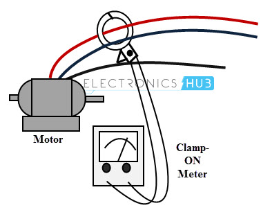
It may be difficult to open a circuit to connect in-line ammeter to measure the current. A new type of test tool that overcomes such problem is the clamp meter which comes with clamp-on current probe with multimeter. These clamp meters either consist clamp probes or inbuilt clamp on the meter (standalone tool) itself as shown in figure.
It may be difficult to open a circuit to connect in-line ammeter to measure the current. A new type of test tool that overcomes such problem is the clamp meter which comes with clamp-on current probe with multimeter. These clamp meters either consist clamp probes or inbuilt clamp on the meter (standalone tool) itself as shown in figure.
The safest and easiest method of measuring the current is the clamp-on probe method than breaking the circuit. Every wire has a magnetic field around it when the current passes through it. When the current flow increases, the magnetic field will also increase. The clamp-on probe measures this magnetic field strength and converts it into corresponding current value. A clamp-on probe meter can measure low currents as well as very high current ranging from less than 1A to 2000A (depends on the manufacturer). It is possible to connect the current probes as input to the DMM operating as voltmeter to find the current. The output of this probe is a voltage which is proportional to the current being measured. The voltage reading on the meter must be converted into current by using current conversion factor. These clamp meters can be analog or digital type. And these are clamped around only one of the lines.
Procedure to Measure Current using Clamp Meter
Decide whether clamp measures AC or DC current or both and determine the type of current being measured by this meter. Connect the black lead of the clamp to COM jack and red one to mA or A jack provided that clamp generates current output. Some clamp accessories produce voltage output; in such case, connect the red probe to V jack. Set the selector switch to DC or AC form of current in case of current output clamp or to DC or AC form of voltage in case of voltage output clamp. Adjusts the current or voltage range to maximum value or to the range suitable to an anticipated maximum range. Clamp the meter to the circuit under measurement and take the reading. Calculate the meter reading based on clamp’s scaling factor.
Make sure to clamp the meter around one of the lines. If meter is clamped around two or more lines, magnetic fields of the wires cancel each other and then meter indicates zero. (Sometimes, meter will show very high current depending on the polarity of the individual magnetic fields). Comment * Name * Email * Website
Δ





![]()