Below charger automatically shut off the charging process when battery attains full charge. This prevents the deep charge of the battery. If the battery voltage is below the 12V, then circuit automatically charges the battery.
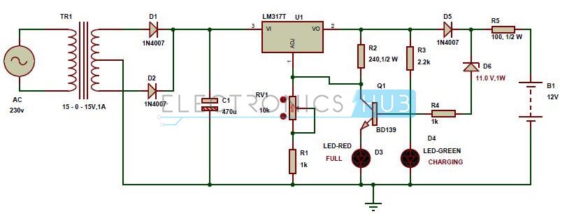
Automatic 12v Battery Charger Circuit Diagram
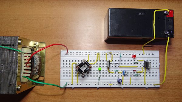
This automatic battery charger circuit is mainly involves two sections – power supply section and load comparison section. The main supply voltage 230V, 50Hz is connected to the primary winding of the center tapped transformer to step down the voltage to 15-0-15V. The output of the transformer is connected to the Diodes D1, D2. Here diodes D1, D2 are used to convert low AC voltage to pulsating DC voltage. This process is also called as rectification. The pulsating DC voltage is applied to the 470uF capacitor to remove the AC ripples. Thus the output of the capacitor unregulated Dc voltage. This unregulated DC voltage is now applied to the LM317 variable voltage regulator to provide regulated DC voltage. The output voltage of this voltage regulator is variable from 1.2V to 37V and the maximum output current from this IC is 1.5A. The output voltage of this voltage regulator is varied by varying the pot 10k which is connected to the adjust pin of LM317. [Also Read: How To Make an Adjustable Timer ] Lm317 voltage regulator output is applied to the battery through the diode D5 and resistor R5. Here diode D5 is used to avoid the discharge of battery when main supply fails. When battery charges fully, the zener diode D6 which connected in reverse bias conducts. Now base of BD139 NPN transistor gets the current through the zener so that the total current is grounded. In this circuit green LED is used for indicating the charge of the battery. Resistor R3 is used to protect the green LED from high voltages.
Output Video:
Circuit Principle
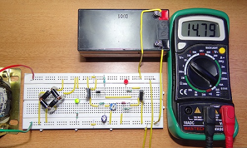
If the battery voltage is below 12V, then the current from LM317 IC flows through the resistor R5 and diode D5 to the battery. At this time zener diode D6 will not conduct because battery takes all the current for charging. When the battery voltage rises to 13.5V, the current flow to the battery stops and zener diode gets the sufficient breakdown voltage and it allows the current through it. Now the base of the transistor gets the sufficient current to turn on so that the output current from LM317 voltage regulator is grounded through the transistor Q1. As a result Red LED indicates the full of charge.
Charger settings
The output voltage of the battery charger should be less than 1.5 times of the battery and the current of the charger should be 10% of the battery current. Battery charger should have over voltage protection, short circuit protection and reversed polarity protection.
2.Automatic Battery Charger
Circuit Diagram
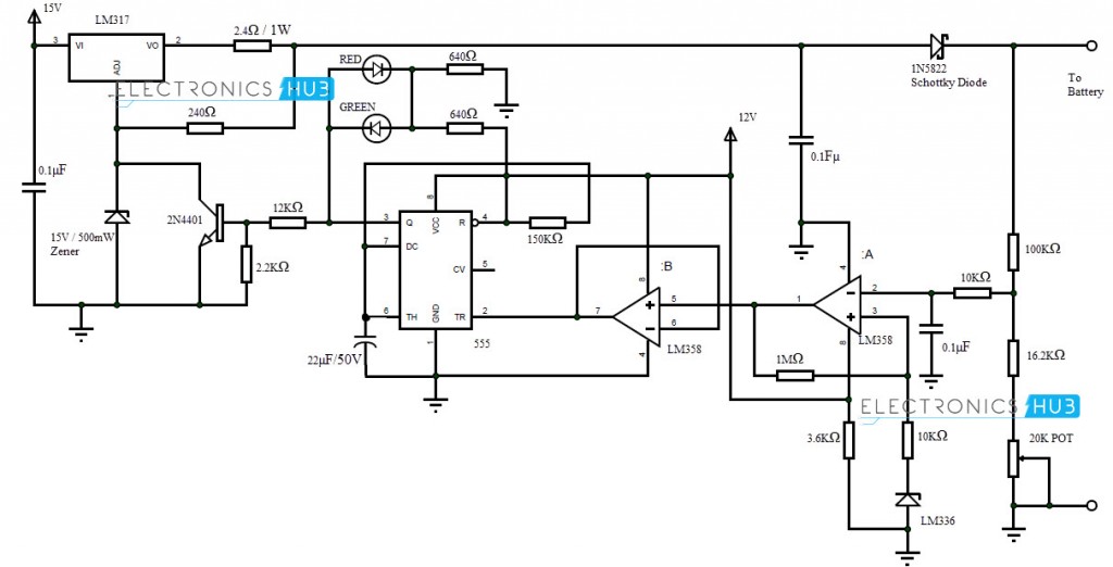
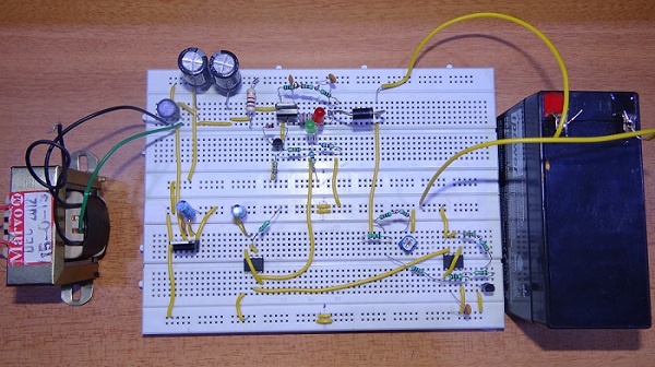
An Automatic Battery Charger Circuit for sealed lead acid batteries is mentioned in this project. It is a pulsed-charger type circuit which helps in increasing the life of batteries. The working of this circuit is explained below. LM317 acts as voltage regulator and current controlling device. The 15V Zener diode is used to set the LM317 to supply 16.2V at output in the absence of load. When the 2N4401 is turned ON by the output of 555, the ADJ pin of the LM317 is grounded and its output voltage is 1.3V. LM358 acts as a comparator and voltage follower. LM336 is used to supply a reference voltage of 2.5V to non-inverting terminal (Pin 3) of LM358. A voltage divider network is used to supply a portion of battery’s voltage to inverting terminal (Pin 2) of LM358. When the charge in the battery reaches 14.5V, the input to inverting terminal of LM358 is slightly greater than 2.5V at Pin 3 set by LM336. This will make the output of 555 go high. As a result Red LED glows and the transistor is turned on. This will ground the ADJ pin of LM317 and its output falls to 1.3V.
When the charge in the battery falls below 13.8V, the output of LM358 is high and the output of 555 is low. As a result, voltage flows from LM317 to battery and Green LED glows to indicate charging. [Related Post– Lead Acid Battery Charger using LM317]
3.Battery charger Using SCR
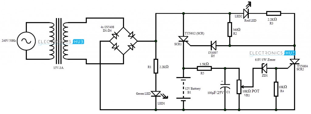
An automatic battery charger circuit using SCR is implemented in this project. It can be used to charge 12V batteries. Batteries with different potentials like 6V and 9V can also be charged by choosing appropriate components. The working of the circuit is as follows. The AC supply is converted to 15V DC with the help of transformer and bridge rectifier and the Green LED is turned on. The DC output is a pulsating DC as there is no filter after the rectifier. This is important as SCR stops conducting only when the supply voltage is 0 or disconnected from supply and it is possible only with pulsating DC. Initially, SCR1 starts conducting as it receives a Gate voltage via R2 and D5. When SCR1 is conducting, 15V DC will flow through the battery and the battery starts to charge. When the charge on the battery is almost full, it opposes the flow of current and the current starts to flow via R5. This is filtered with C1 and when the potential reaches 6.8V, Zener ZD1 starts conducting and supplies enough Gate voltage to SCR2 to turn it on. As a result, the current flows through SCR2 via R2 and SCR1 is turned off as both gate voltage and supply voltage are cut off. The Red LED is turned on indicating a full charge on the battery.
Know how to design a circuit of auto cut-off and auto charging of a battery using SCR. Any help would be appreciated . I am trying to design a circuit to charge (2) 12 volt 10aH sla batteries using the power from bicycle pedaling,
- On Charge LED emitted continuously. 2) Full charge LED does not work. The value of resisters and zener varies from schematic to your you tube video. Kindly Help. Regards, Best Regards. Comment * Name * Email * Website
Δ





![]()