Introduction
Measuring Voltage, Current and subsequently the Power is an essential task of any electronics engineer. For measuring voltage and current, you can use simple handheld multimeters as they provide both the range and accuracy for normal usage. But in order to measure power, you have several options like simple wattmeters to complex power analyzers and power meters. What if I told you that you can make your own Wattmeter with simple components as a DIY Project, which can be used in your LED or Solar related projects? Instead of buying a readily available and an expensive Wattmeter, you can easily make your own Arduino Wattmeter. I will explain all necessary steps required for the same.
Concept of Arduino Wattmeter Project
There are number of ways that you can implement the Arduino Wattmeter Project. One of the easy ways is to interface a Voltage Sensor and a Current Sensor with Arduino, measure the voltage and current values and finally with some mathematics, you can calculate the Power in Watts.
Although using sensors can provide accurate results, where is the fun in using sensors if you can build the entire system yourself. This is beneficial if you are a student and trying to grab the underlying concepts. The method which I will be implementing involves complete design of the circuit. For ease of understanding I will divide the circuit into two halves: The Sensor part and The Control Part. The Sensor Part of the circuit is responsible for measuring the Voltage across the load and Current through the load. Both these values, which are analog in nature, are given to the Arduino to its ADC. Arduino converts these values to digital values and makes a few calculations as displays the results on the LCD.
Circuit Diagram
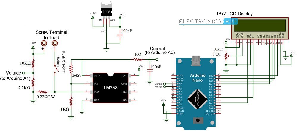
The following image shows the circuit diagram of Arduino Wattmeter.
Components Required
Arduino UNO or Nano 16×2 LCD Display LM358 Op Amp 7805 Voltage Regulator Resistors – 0.22Ω/3W, 1KΩ x 2, 2.2KΩ, 10KΩ, 20KΩ 10KΩ Potentiometer Capacitors – 100nF x 2 (0.1µF – Code 104) Push ON – Push OFF Button Connecting Wires Terminals for connecting Load 12V Power Supply
Code
The code for project is given below.
Working of Arduino Wattmeter
In the sensor part of the circuit, there are two areas which are responsible for measuring voltage and current. For measuring the voltage, a voltage divider circuit is implemented using a 10KΩ and a 2.2KΩ Resistor.
Using these resistors, you can measure voltages up to 24V. These resistors also help us bringing the voltage range to 0V – 5V, which is the range Arduino works on. Now, coming to the current measurement, Arduino or any Microcontroller for that matter can only accept analog voltage as input i.e. it can only read voltages. If Arduino can only read voltages, then how can we measure current? In order to measure current, you have to convert the current values to appropriate voltage values. Here comes the Ohm’s Law to the rescue. As per Ohm’s Law, the voltage drop across a load is proportional to the current. Hence, a small shunt resistor is placed with respect to the load. By measuring the voltage across this resistor, you can measure the current. The shunt resistor used here is of 0.22Ω (3W). Even when the load draws a current of 1A (which is the theoretical limit of this circuit and shouldn’t exceed this value), the voltage across the shunt resistor is only 0.2V. This value is very low for Arduino’s ADC circuit. Hence, I have used LM358 Op Amp in Non-Inverting Amplifier Mode to amplify the values provided to Arduino. The voltage divider network for the feedback control consists of 20KΩ Resistor and 1KΩ Resistor. These resistors contribute to a gain of approximately 21.
Output of the Amplifier is filtered and given to Analog Input pin of Arduino. Arduino takes both the voltage and current (masked as voltage) values at Analog Input pins A1 and A0 respectively. After performing few calculations, it then displays the values of Voltage, Current and Power on the LCD Display.
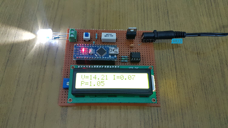
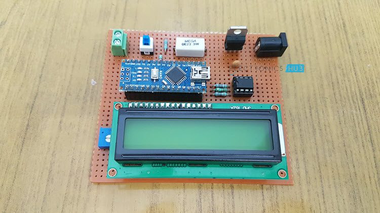
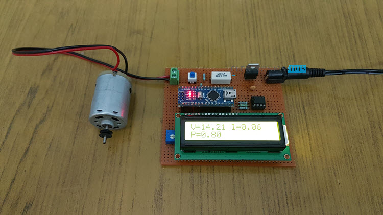
Testing Arduino Wattmeter Circuit
After designing the circuit on a perf board and making all the necessary connections, I have used the circuit to test a couple of loads like LED and a Motor. I have used a 12V Power supply and all the results are satisfactory.
Output Video
Conclusion
A simple Arduino Wattmeter is designed in this project with the aim of measuring power consumed by small loads (up to 12W). In a future implementation, as an extension to this project, I will design a new circuit based on Voltage and Current Sensors for more accurate results. In the code, you have used Voltage = Voltage * (5.0/1023.0) * 6.46; Current = Current * (5.0/1023.0) * 0.239; 6.46 and 0.239 multiplier. how to get that ? and how you have converted voltage into current ? Comment * Name * Email * Website
Δ
![]()
![]()
![]()
![]()
![]()

