Principle Behind Power Amplifier Circuit:
The basic principle behind this circuit is the different ways of biasing of a bipolar junction transistor. The electric signal output from a microphone is very low. This low voltage signal is amplified to a sustainable level using the CE configuration of a BJT, biased in class A mode. In this mode, the output is an inverted amplified signal. This signal is a low power signal. Two Darlington power transistors arranged in class AB configuration amplify the power level of this signal. A transistor configured in class A mode is used to drive this transistor.
Theory Behind Power Amplifier Circuit:
Two important aspects of this circuit are class AB amplifiers and class A voltage amplifiers. A transistor biased in class AB mode produces an amplified output signal for only one half of the input signal. Thus a AB amplifier consists of two matched transistors such that one conducts for one half of the input signal and another conducts for the second half. A practical class AB amplifier consists of diodes to provide biasing to the two transistors, so as to eliminate the cross over distortion. This amplifier is driven by a transistor arranged in common emitter configuration. A transistor biased in class A mode produces an inverted version of the input signal. However the efficiency is low and so is the output impedance.
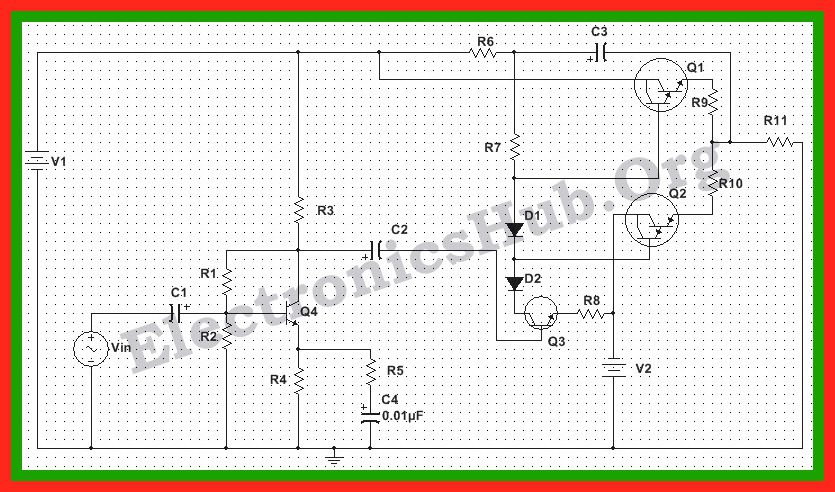
Circuit Diagram of 150W Power Amplifier Circuit:
Power Amplifier Circuit Design:
This gives, R1 = (Vcc-Vb)/Ie = 24.5K. Here we select a 25K resistor R2 = Vb/Ie = 3.35K. Here we select a 3K resistor.
Testing the Power Amplifier Circuit:
Once the circuit is designed and drawn on Multisim, the input is given by connecting a AC signal voltage source to the coupling capacitor of the preamplifier stage. The input is set at 4Vpp, 1kHz. The output is determined by connecting a Wattmeter such that voltage terminals are connected across the load resistor of 8Ohms and the current terminals are connected between the output terminal and the load resistor. Here we observe the maximum output power to be around 200W.
Applications of Power Amplifier Circuit:
Comment * Name * Email * Website
Δ
![]()
![]()
![]()
![]()
![]()

