Subwoofer Amplifier Circuit Principle
Audio Signal is first filtered to remove the high frequency signals and allow only the low frequency signals to pass through it. This low frequency signal is then amplified using a voltage amplifier. This low power signal is then amplified using a transistor driven class AB power amplifier.
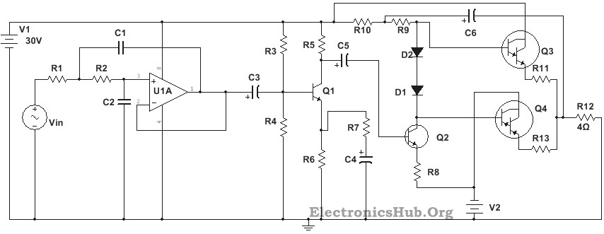
Circuit Diagram of 100W Subwoofer Amplifier
Circuit Components:
ComponentValue R16K R26K R3130K R422K R515K R63.2K R7300 Ohms R830 Ohms R9, R103 K C1, C20.1uF, electrolyte C3,C5,C610uF, electrolyte C41uF, electrolyte Q12N222A Q2TIP41 Q3TIP41 Q4TIP147, PNP D1, D21N4007 Dual Supply+/-30V
Subwoofer Amplifier Circuit Design:
Audio Filter Design:
Here we designed a Sallen Key low pass filter using OPAMP LM7332. The cut off frequency was assumed to be 200Hz and the Quality factor is assumed to be 0.707. Also assuming the number of poles to be equal to 1 and value of C1 to be equal to 0.1uF, value of C2 can be calculated to be 0.1uF. Assuming R1 and R2 to be same, the value can be found by substituting known values in the equation R1 = R2 = Q/(2pifc*C2) This gives a value of 5.6K for each resistor. Here we select 6K resistors as R1 and R2. Since we want a closed loop gain filter, we do not require resistors at the non inverting terminal, which is shorted to the output terminal.
Pre Amplifier Design:
The preamplifier is based on class A operation of transistor 2N222A. Since the required output power is 100W and load resistor is 4 Ohms, here we require a supply voltage of 30V. Assuming the collector quiescent current to be 1mA and collector quiescent voltage to be half of supply voltage, i.e.15V, the value of load resistor is calculated to be equal to 15K. R5 = (Vcc/2Icq) Base current is given by, Ib = Icq/hfe Substituting the values, hfe or AC current gain , we get the base current to be equal to 0.02mA. The bias current, Ibias is assumed to be ten times the base current, i.e. 0.2mA. The emitter voltage is assumed to be 12% of the supply voltage, i.e. 3.6V. The base voltage, Vb is then equal to Ve +0.7, i.e. 4.3V. Values of R3 and R4 are then calculated as given: R3 = (Vcc – Vb)/ Ibias and R4 = Vb/Ibias Substituting the values, we get R3 to be equal to 130 K and R4 to be equal to 22K The emitter resistor is calculated to be equal to 3.6K (Ve/Ie). However this resistance is shared between two resistors, R6 and R7, where R7 is used as feedback resistor to reduce the decoupling effect of C4. Value of R7 is calculated by the values of R5 and gain and found to be equal to 300Ohms. Value of R6 is then equal to 3.2K. Since capacitive reactance of C4 should be less than the emitter resistance, we calculate the value of C4 to be equal to 1uF.
Power Amplifier Design:
The power amplifier is designed using Darlington transistors TIP142 and TIP147 in class AB mode. The biasing diodes are selected such that their thermal properties are equal to that of the Darlington transistors. Here select 1N4007. Since a large value of bias resistor is required for a low bias current, we select R9 to be equal to 3K. The driver stage is used to provide a high impedance input to the power amplifier. Here we use a power transistor TIP41 in class A mode. The emitter resistor, R8 is given by the values of emitter voltage, Ve (1/2Vcc- 0.7) and emitter current, Ie (equal to collector current, i.e. 0.5A) and is found to be equal to 28.6 Ohms. Here we select a 30 Ohms resistor. The value of bootstrap resistor R10 should be such that to be provide high impedance to the Darlington transistors. Here we select R10 to be 3K.
Subwoofer Amplifier Circuit Operation:
The audio signal is filtered by the Sallen Key low pass filter using the OPAMP such that only frequencies below and equal to 200Hz are passed and remaining filtered. This low frequency signal is given to the input of the transistor Q1 through the coupling capacitor, C3. The transistor operates in class A mode and produces a amplified version of the input signal at its output. This amplified signal is then converted into a high impedance signal by Q2 and is given to the class AB power amplifier. The two Darlington transistors operate such that one conducts for positive half cycle and other for negative half cycle, thus producing a full cycle of output signal. The emitter resistors R11 and R13 are used to minimize any difference between the matching transistors. The diodes are used to ensure minimal cross over distortion. This high power output signal is then used to drive a loudspeaker or subwoofer of low impedance, about 4 Ohms. Note that here we have used an 8 Ohm resistor for testing purpose.
Applications of Subwoofer Amplifier Circuit:
Comment * Name * Email * Website
Δ
![]()
![]()
![]()
![]()
![]()

